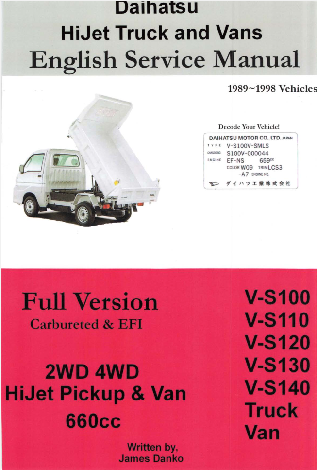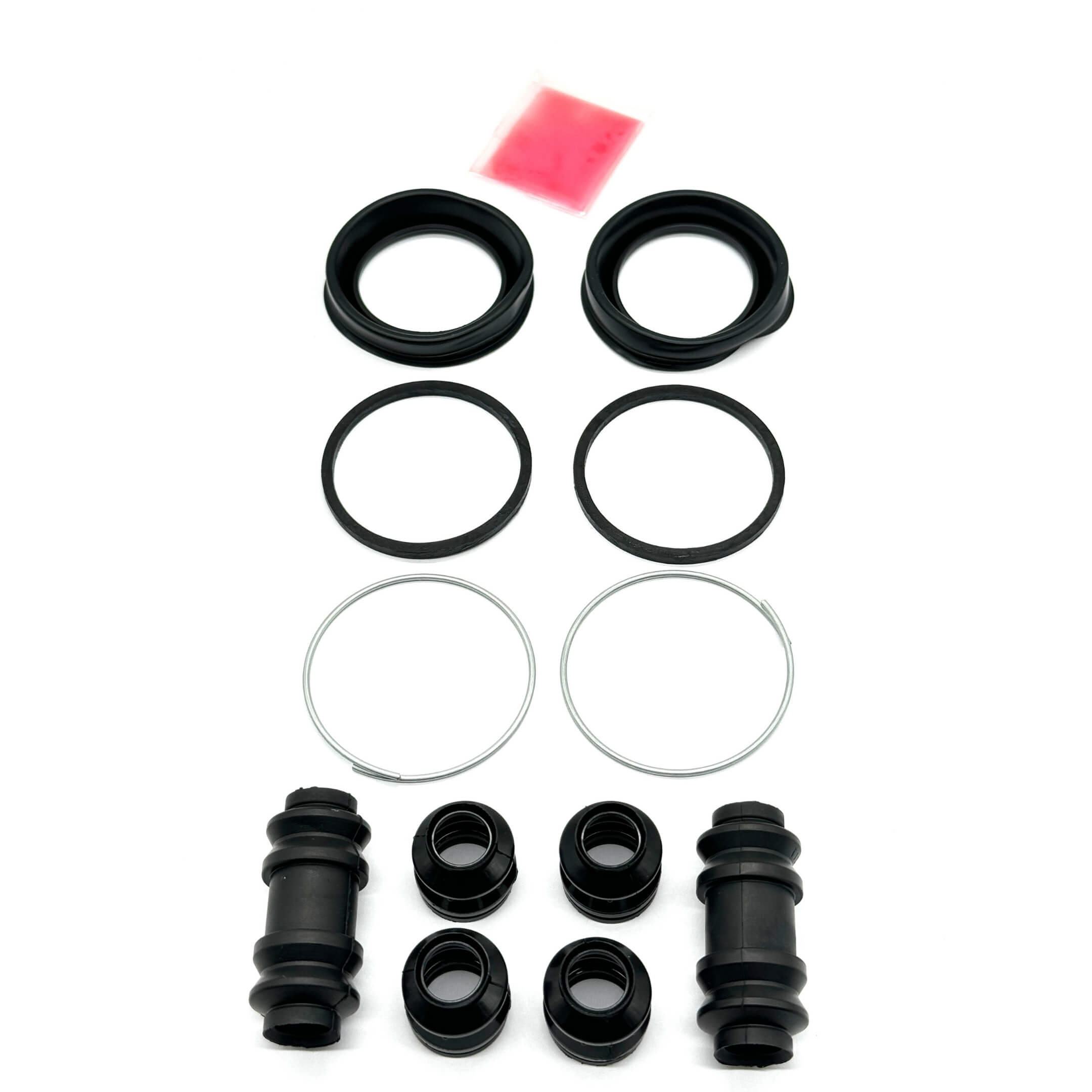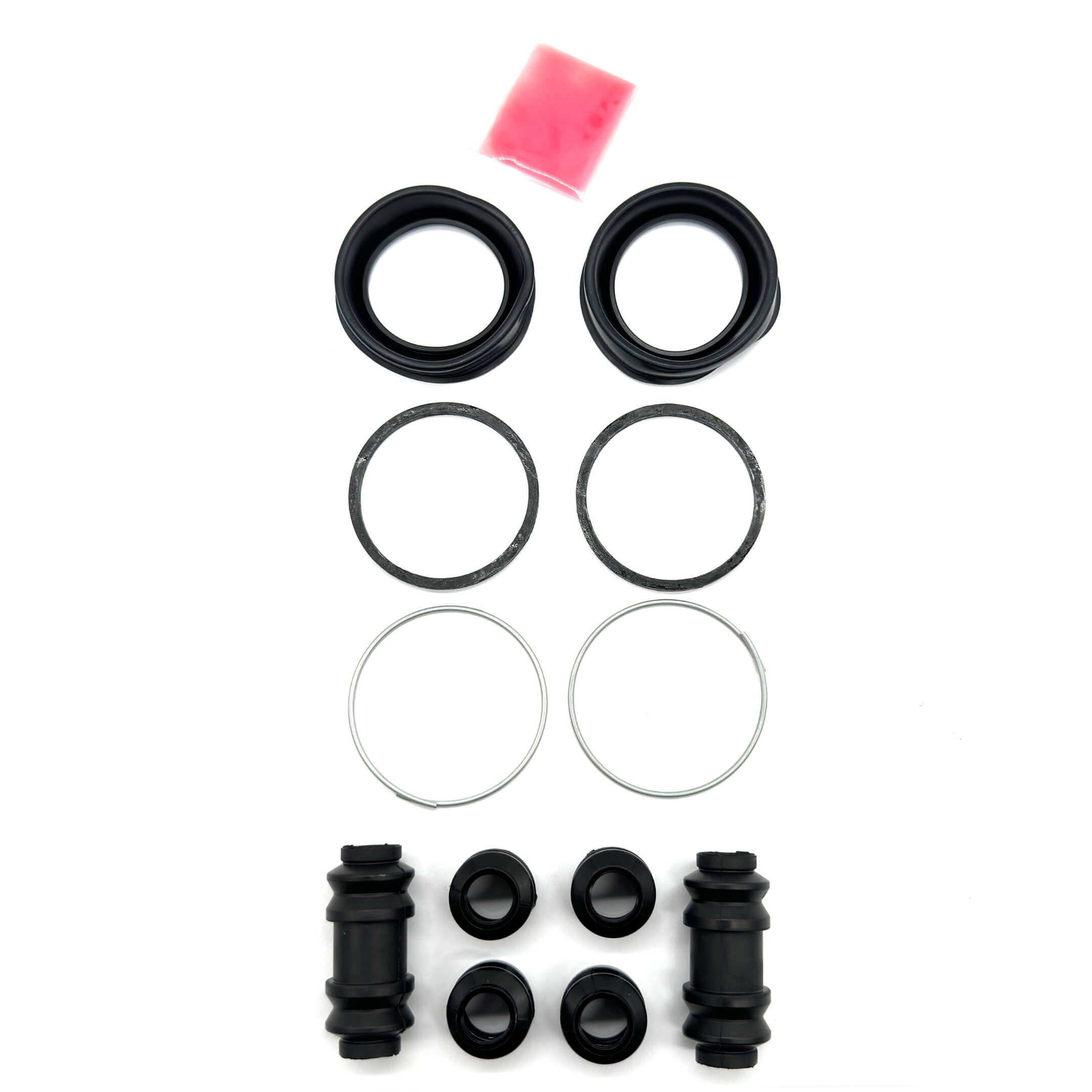
Daihatsu Hijet Brake Parts - S100, S110 Models - 1994-1998
Front disc components, rear drum parts, hydraulics, lines, hoses, parking-brake cables, pedal parts, plus service kits. Confirm the full CHASSIS NO., body style, brake setup, and position before ordering.
Front disc components, rear drum parts, hydraulics, lines, hoses, parking-brake cables, pedal parts, plus service kits. Brake fitment follows the full CHASSIS NO., drivetrain, body style, booster configuration, brake system, plus position or side. Model year alone does not confirm every brake part.
Confirm the full CHASSIS NO., body style, brake setup, and position before ordering.
Find Your Truck
Before ordering, confirm the complete CHASSIS NO./model code, drivetrain, body style, brake configuration, booster setup, plus required position or side.


| Fitment Check | What to Confirm | Parts Affected |
|---|---|---|
| Model / chassis code | S100P/S110P identify pickups; S100V/S110V identify vans. Read the complete prefix from the identification plate. | Establishes the model family before checking individual brake parts. |
| Drivetrain | S100 is 2WD. S110 is 4WD. | Changes front hub/rotor arrangement plus some parking-brake cable routing. |
| Body style | Confirm pickup, van, or cab-chassis. Pickups use a WP valve. Van applications use an LSPV; Atrai material is factory reference only. | Changes front caliper design, pad/shim layout, slide-pin torque, plus rear pressure control. |
| Brake system | S100/S110 buying fitment uses the standard brake system. S120/S130 ABS information later on this page is factory reference only. | Prevents S120/S130 ABS reference material from being treated as S100/S110 buying fitment. |
| Booster configuration | Standard systems use 6- or 7-inch booster diameters. The 8-inch booster belongs with the anti-lock configuration. | Determines the correct booster/master-cylinder pairing plus applicable repair parts. |
| Position / side | Front brakes are disc. Rear brakes are drum. Some rear wheel cylinders and parking-brake cables are side-specific. | Select front or rear first, then confirm left/right or cable position where required. |
S120/S130 ABS content is reference only, not S100/S110 fitment.
Choose Your Parts
Use the fitment checks above first. This table shows each product category plus the fitment distinction that matters most.
| Category | What You Get | Fitment |
|---|---|---|
| Front Brakes | Brake pads, rotors, caliper pistons, piston sets, seal kits, rebuild kits, bleeder screws. | Confirm body style for caliper/pad design, then confirm the model and front position. |
| Rear Brakes | Brake shoes, left/right wheel cylinders, wheel-cylinder sets, cup kits. | Rear brakes are drum. Confirm model plus side where applicable; choose rebuild parts only after inspecting cylinder condition. |
| Brake Kits | Front 6-, 8-, and 21-piece kits; 6-piece rear kit; 27-piece kit covering both axles. | Confirm axle coverage plus exact model fitment on the product listing. |
| Hydraulics | Master cylinders, repair kits, brake boosters, pressure-control parts where offered. | Confirm booster diameter, body style, rear pressure-control layout, plus the applicable S100/S110 system. |
| Lines & Hoses | Front/rear line sets, individual lines, complete vehicle kits. | Routing follows drivetrain plus body. Confirm the chassis code before ordering a complete line set. |
| Parking Brake | Front cable, rear left/right cables, three-piece kit, seven-piece cable/line kit. | Confirm cable number or side. The center clamp position differs between 2WD and 4WD. |
| Pedal & Switches | Brake pedal pads, brake/clutch pedal pad sets, brake-light switch. | Confirm the exact pedal or switch application before ordering. |
Which brake part do you need?
Use a confirmed measurement or test result, not a symptom alone, to choose the replacement part.
| Confirmed Finding | Typical Part Needed |
|---|---|
| Front pad at or below 1 mm minimum | Front brake pads |
| Front rotor at or below 11 mm minimum thickness | Front brake rotor |
| Rear shoe at or below 1 mm minimum lining | Rear brake shoes |
| Rear drum at or above 181 mm maximum inside diameter | Rear brake drum |
| Confirmed wheel-cylinder leak | Wheel cylinder or applicable rebuild parts, depending on bore condition |
| Confirmed damaged brake hose | Brake hose |
| Confirmed master-cylinder fault | Master cylinder or applicable repair kit |
| Confirmed booster or vacuum-system fault | Booster or vacuum-system component |
| Confirmed seized parking-brake cable after shoe, adjuster, and movement checks | Parking-brake cable |
Wear & Service Limits
Use measurements for wear parts. Fluid, hoses, rubber parts, booster components, plus rear pressure-control parts also have service intervals.
Wear limits
| Part | Factory Standard | Service Limit | Action |
|---|---|---|---|
| Front brake pad lining | 10 mm | 1 mm minimum | Replace at 1 mm or less, or sooner for cracking, severe uneven wear, or contamination. |
| Front solid brake disc | 12 mm | 11 mm minimum | Replace at 11 mm or less. The manual does not publish a machining allowance. |
| Front disc runout | - | 0.10 mm maximum | Measure with the gauge 10 mm in from the outer edge. Inspect hub and bearing if runout is excessive. |
| Rear brake shoe lining | 4 mm | 1 mm minimum | Replace at 1 mm or less, or for severe uneven wear. Replace left/right shoes as a set. |
| Rear brake drum | 180 mm | 181 mm maximum | For severe uneven wear, the factory says machine or replace the drum. No machining allowance is printed; never exceed 181 mm. |


Two more brake checks
A front disc must pass both thickness and runout checks. If runout exceeds 0.10 mm, inspect the hub plus wheel bearing before replacing the disc.
Rear shoes also require a contact-pattern check. Chalk the drum inner surface, fit the shoe, inspect the transferred pattern, then remove all chalk after the check.
Time-based service
| Part | Private Use | Commercial Use | Notes |
|---|---|---|---|
| Brake fluid | 2 years | 1 year | Replace regardless of appearance. |
| Brake hoses | 4 years | 2 years | Replace sooner if cracked, swollen, or leaking. |
| Master-cylinder and wheel-cylinder rubber parts | 2 years | 1 year | Includes cups, boots, plus related rubber components. |
| Brake-booster rubber parts | 4 years | 2 years | Replace at the listed age interval. |
| Brake-booster vacuum hose | 4 years | 2 years | Replace sooner if the one-way valve fails. |
| Rear pressure valve | 4 years | No separate interval listed | The manual calls this the P valve. |
Related front-hub service
Replace the front wheel-bearing grease every 30,000 km or 2 years, whichever comes first. This is directly relevant when brake-disc service requires hub disassembly.
Front & Rear Brakes
Front brakes use solid discs. Rear brakes use leading/trailing shoes in drums. Body style changes the front caliper design, pad/shim layout, plus some service torque values.
Front disc brakes
Pickups use one front caliper design. Vans use another; Atrai material is factory reference only. Each pad uses a wear indicator plus inner and outer anti-squeal shims. Install both shims.


Keep oil or grease off the pad linings and disc surfaces. Lubricants used on slide pins, bushings, or seals must stay away from friction faces.
Removing a caliper piston
Feed compressed air slowly through the union-bolt hole with a wood block restraining the piston. Prevent uncontrolled piston ejection.
Practical service guidance: if the piston is heavily seized, replace the piston or complete caliper rather than assuming a seal kit will repair it.
Rear drum brakes
Each rear brake uses leading and trailing shoes, one wheel cylinder, plus an automatic adjuster. The parking brake acts through the same shoes.
After reassembly and bleeding, press the pedal two or three times to set shoe clearance before evaluating pedal travel.


- Cotter pin
- Castle nut
- Brake drum subassembly
- Brake shoe hold-down spring
- Brake shoe hold-down spring pin
- Tension spring
- Tension spring
- Tension spring
- Brake shoe assembly No. 1
- Brake shoe assembly No. 2
- Parking brake shoe strut
- Parking brake shoe lever
- Rear wheel brake cylinder assembly
- Automatic adjuster latch
- Automatic adjuster lever
- Torsion spring
- Automatic adjuster lever pin
- Brake backing plate
A mark beside a number in the factory illustration identifies a single-use part. The cotter pin plus type-C retaining washers are examples that should be on hand before service.
Rear wheel cylinder
Each wheel cylinder contains two pistons, two cups, a center spring, plus one boot at each end. Use a cup kit only when the bore is smooth.
Practical service guidance: replace the complete wheel cylinder if the bore is pitted or scored, because new cups will not seal reliably on a damaged bore.
Use brake grease on specified mechanical/backing-plate contact points. Use rubber grease on specified wheel-cylinder rubber parts. Never put either on a friction surface.
Hydraulics & Controls
Hydraulic fitment depends on body style, rear pressure-control layout, booster diameter, plus the master-cylinder configuration paired with that booster.
Master cylinder & booster

The 6-, 7-, and 8-inch dimensions refer to brake booster diameter, not master-cylinder bore size. Standard systems use 6- or 7-inch boosters. The 8-inch configuration belongs with anti-lock equipment.
Run the engine 1–2 minutes, shut it off, then press several times with equal force at least five seconds apart. The pedal should rise as stored vacuum is depleted.
Hold the pedal down with the engine off, then start the engine. The pedal should sink slightly. With the engine running, press the pedal, shut the engine off, then hold for 30 seconds. The pedal should not move.


The clearance between the booster pushrod and the master cylinder piston is set to zero.
Booster vacuum hose
The hose contains a directional one-way valve. Air must flow from the booster toward the engine, never in reverse. Replace the hose if air passes both ways. The factory also specifies age-based replacement in the service table above.
Rear pressure control
| Models | Valve | How It Controls Rear Pressure |
|---|---|---|
| S100P and S110P pickups | WP valve | Uses a fixed pressure curve. Rear pressure matches front pressure up to 13.5 kgf/cm² , then increases more slowly to reduce rear-wheel lockup. |
| S100V and S110V vans | LSPV | A spring linked to the rear axle adjusts rear brake pressure based on vehicle load. More weight allows greater rear pressure. |
| Atrai models | LSPV | Uses the same load-sensing design, but its factory pressure standards differ from standard vans. |
S120/S130 vans use the same load-sensing design in the ABS factory reference but remain outside S100/S110 buying fitment. The Atrai row is comparison material.


The sensor spring links the valve to the rear axle. Its position tells the valve how much load is over the rear wheels.
Do not treat the adjusting bolt as a mounting fastener. Before removal, measure and record spring height. Reinstall it at the same height with the retaining hook facing outward. Recheck the setting after work that changes rear-axle position.
Brake pedal
| Check | Factory Standard | Test Conditions |
|---|---|---|
| Brake-pedal free play | 2.5 ± 1.5 mm | Remove stored booster vacuum before measuring. |
| Installed pedal height | Factory conflict | Factory sources print 140 ± 00 mm and 185 ± 35 mm. See Factory Notes. |
| Pedal reserve clearance | 98 mm minimum | Engine running, parking brake released, 50 kgf applied. |

Parking brake
Three cables connect the lever to the rear brakes. Cable No. 1 runs from the lever to the rear junction. Cables No. 2 and No. 3 continue to the rear wheels.
| Cable | Position | Function |
|---|---|---|
| No. 1 | Front | Connects the parking-brake lever to the rear cable junction. |
| No. 2 | Rear | Connects the junction to one rear wheel. |
| No. 3 | Rear | Connects the junction to the opposite rear wheel. |
For excessive travel, press the brake pedal two or three times, inspect rear-shoe wear, confirm shoe clearance, check the automatic adjuster, inspect cable movement, then adjust the parking brake last.
| Check | Factory Standard | Test Conditions |
|---|---|---|
| Parking-brake travel | 6 to 10 notches | 20 kgf operating force; full mechanical stroke is 19 notches. |
| Parking-brake slope test | Holds on a paved 1-in-5 slope | Vehicle must remain stationary. |
| Parking-brake tester result | At least 20% of vehicle weight | Lever force must not exceed 50 kgf. |
Tighten the lever mounting bolts plus each cable clamp to 75 ± 15 kgf-cm. The center clamp position differs between 2WD and 4WD; the cables themselves are the same parts.
Troubleshooting
A symptom identifies what to inspect, not one failed part. Follow the order, then confirm the cause by measurement or test before ordering.
| What You Notice | What to Inspect, in Order |
|---|---|
| Soft or spongy pedal | Fluid level, external leaks, trapped air, rear shoe clearance, automatic adjuster, then flexible hoses. |
| Pedal sinks under steady pressure | External leaks first, then internal master-cylinder bypass. |
| Hard pedal with weak stopping | Booster operation, vacuum hose, one-way valve, then engine vacuum supply. |
| Too much pedal travel | Fluid level, external leaks, trapped air, rear shoe clearance, automatic adjuster, then pedal free play. |
| Pulls to one side | Left-to-right tire condition, contaminated pads or shoes, caliper or wheel-cylinder movement, then a restricted hose. |
| Grinding | Pad or shoe thickness first, then rotor or drum damage. |
| Squealing | Pad thickness, wear indicator, anti-squeal shims, glazing, then contamination. |
| Pulsation through the pedal | Front wheel-bearing play, disc runout, hub runout, then rear drum condition. |
| One wheel drags or stays hot | Restricted hose, sticking caliper piston or slide pins, rear shoe return parts, wheel cylinder, then parking-brake cable. |
| All brakes drag | Pedal free play, booster pushrod adjustment, then master-cylinder return operation. |
| Visible fluid loss | Reservoir and master cylinder, pipe unions, hoses, calipers, then rear wheel cylinders. |
| Weak parking brake | Rear shoe thickness or contamination, automatic adjuster, lever travel, then cable condition. |
| Parking brake will not release | Cable seizure, lever return, shoe lever and strut, then return springs. |
| Brake warning lamp stays on | Parking brake fully released, fluid level, fluid-level switch, parking-brake switch, then wiring. |
| ABS warning lamp stays on (S120/S130 reference) | Release direct-coupled 4WD where applicable, read the diagnostic codes, then inspect the relay, fuse, sensors, plus wiring. |
Do not drive with active fluid loss, a sinking pedal, grinding brakes, or a wheel that remains hot.
S120 / S130 ABS factory reference
This ABS material is outside S100/S110 buying fitment. It is retained only as factory reference for S120/S130 vans.
ABS was available on S120 and S130 vans. The system uses four wheel-speed sensors, four sensor rotors, a G sensor, an actuator with three solenoid valves plus a pump, one relay, and a control unit under the console.
What the ABS warning lamp means
Turn the ignition ON. The ABS lamp should light for about three seconds, then turn off. If it never lights, inspect the bulb, fuse, plus related wiring.
A lamp that stays on may indicate an ABS fault, warning-lamp circuit short, or locked center differential. On an ABS fault, the computer turns the ABS relay off; conventional braking remains but anti-lock control is unavailable.
A flashing lamp while stopped usually means the diagnostic connector remains shorted. Check Tc-to-E1 or Ts-to-E1; without a jumper, inspect those circuits for a short to ground.
On Multi-Select 4WD models, selecting 4WD alone should not illuminate the lamp while the center differential remains unlocked. Locking the center differential turns the lamp on after about one second and stores code 48 . Release the lock to restore ABS operation. When the system is normal, code 48 clears after the ignition is turned off.
Testing ABS circuits with the computer disconnected
Turn the ignition OFF. Disconnect the ABS computer plus test harness, then measure at the vehicle-side connector. An incorrect reading identifies a circuit to inspect, not necessarily a failed component; check wiring and connectors first.
| Circuit Tested | Measure Between | Factory Standard | Inspect if Out of Specification |
|---|---|---|---|
| Right-front speed sensor | Pins 32 FR+ and 11 FR− | 0.7 to 1.5 kΩ | Sensor, wiring, or connectors |
| Left-front speed sensor | Pins 17 FL+ and 38 FL− | 0.7 to 1.5 kΩ | Sensor, wiring, or connectors |
| Right-rear speed sensor | Pins 8 RR+ and 29 RR− | 0.7 to 1.5 kΩ | Sensor, wiring, or connectors |
| Left-rear speed sensor | Pins 22 RL+ and 1 RL− | 0.7 to 1.5 kΩ | Sensor, wiring, or connectors |
| Front-right solenoid | Pins 9 SFR and 34 AST | About 6 Ω | ABS actuator circuit |
| Front-left solenoid | Pins 21 SFL and 34 AST | About 6 Ω | ABS actuator circuit |
| Rear solenoid | Pins 42 SRR and 34 AST | About 6 Ω | ABS actuator circuit |
| Pump-motor winding | Pin 14 MT to body ground | About 7 Ω | ABS actuator circuit |
| AST circuit | Pin 34 AST to body ground | About 5 Ω | ABS actuator circuit |
| Solenoid-relay coil | Pins 19 SR and 40 R− | 60 to 100 Ω | ABS relay circuit |
| Motor-relay coil | Pins 39 MR and 40 R− | 50 to 80 Ω | ABS relay circuit |
A wheel-speed sensor tested directly at its connector should measure 1.1 ± 0.4 kΩ , which is the same 0.7 to 1.5 kΩ range. A correct reading at the sensor but an incorrect reading at the computer connector points to the wiring or connectors between them.
A direct-power test can confirm that the actuator pump motor runs. It does not confirm hydraulic pressure, solenoid operation, or complete actuator function. Follow the factory terminal and polarity instructions before applying battery voltage.
Three ABS faults often misdiagnosed
| Common Misdiagnosis | What the Manual Shows | Check First |
|---|---|---|
| A damaged sensor rotor means the sensor has failed | The sensor rotor is separate from the electrical sensor. Damaged, dirty, or missing rotor teeth can produce the same fault as a failed sensor. The manual does not confirm whether the rotors were sold separately. | Inspect the rotor teeth, sensor mounting, wiring, plus resistance before replacing the sensor. |
| Zero voltage at several solenoid terminals means multiple parts failed | During fail-safe operation, the computer switches the ABS relay off and stops the solenoid control signals. Several terminals may therefore show no voltage from one stored fault. | Read the diagnostic code, repair the original fault, then repeat the voltage tests. |
| ABS that activates late must have a bad actuator | ABS control cannot begin until the computer receives the stop-lamp switch signal. An open, misadjusted, or faulty switch can delay activation. | With the ignition off while the pedal is pressed, measure between computer terminals 6 STP and 10 GND . The factory standard is 10 to 14 V . |
Handling ABS components
The ABS computer and sensors are precision parts. Do not reuse a computer or sensor that has been dropped or heavily impacted, even when no damage is visible.
Store the G sensor upright, protect it from water, and never apply 6 V or more . Its normal test supply is 4.5 to 5.5 V .
Do not open the computer cover or disassemble the ABS actuator. Turn the ignition off before unplugging connectors, or disconnect the battery negative terminal. Disconnecting a component with the ignition on can trigger fail-safe mode and store a fault code.
Installation & Bleeding
Brake service requires correct fitment, factory wear limits, the specified single-use hardware, plus final leak and function checks.
Single-use parts
| Service operation | Parts that must be replaced |
|---|---|
| Brake pedal linkage, when disconnected | The unnumbered retaining cotter pin shown beside the pin connecting the brake pedal to the booster pushrod. |
| Master cylinder, during a full rebuild | Reservoir grommet, set bolt, set-bolt gasket, internal snap ring, plus piston assemblies No. 1 and No. 2. The factory requires new piston assemblies rather than cleaned originals. |
| Brake booster, during a rebuild | Brake booster body No. 2 seal. |
| Front caliper, during a rebuild | Piston seal, cylinder boot, plus bushing dust boot. |
| Front hub or rotor, when removed | Cotter pin securing the hub castle nut. |
| Front brake hose, when disconnected from the caliper | Brake-hose union-bolt gasket. |
| Rear drum, when disassembled | Rear hub cotter pin, both brake-shoe hold-down springs, parking-brake lever type-C washer, plus the automatic-adjuster type-C washer or retaining clip. |
Bleeding the brakes
The factory material requires bleeding but does not publish a complete standalone sequence. Do not invent a wheel order, pedal count, pressure-bleeder method, or vacuum-bleeder method.
- Seat disconnected brake tubes correctly. Start the union nut by hand until the flare seats fully. Tighten it to 155 ± 25 kgf-cm , about 15.2 ± 2.5 N·m or 11.2 ± 1.8 lb-ft .
- Fill the reservoir to MAX. Recheck the level after bleeding.
- Bleed the system. The manual does not provide a method or wheel order.
- Recheck ABS systems for trapped air. ABS systems take longer to clear. Continue bleeding if air remains.
- Check pedal feel. A soft or spongy pedal means air may remain.
- Inspect every disturbed connection for leaks.
- After rear drum service, press the pedal two or three times. This operates the automatic adjuster and sets shoe clearance.
- Confirm that no brake drags.
- Test braking at low speed on a level road. The truck should stop normally without pulling.
Retracting a caliper piston
Loosen the bleeder plug before pressing the piston inward. Let the displaced fluid escape through the bleeder instead of forcing it back through the system.
After installation, refill the reservoir to MAX, bleed the brakes, then confirm the wheel turns without drag.
The bleeder itself goes back to 85 plus or minus 15 kgf-cm, roughly 6 lb-ft, so it is a gentle fitting rather than something to lean on.
How to tell air may still be in the system
Practical diagnostic guidance: after bleeding, the pedal should feel firm and consistent. A soft or springy pedal that improves when pumped may indicate trapped air. Excessive rear-shoe clearance can produce a similar symptom, so inspect the rear adjusters as well.
A pedal that slowly sinks under steady pressure points to hydraulic pressure loss. Check for external leaks before inspecting the master cylinder for internal bypass.
After LSPV service
The factory LSPV removal procedure requires bleeding but omits the rest of the post-installation sequence. Practical final checks are:
- Fill the reservoir to MAX .
- Bleed the brake system.
- Check every disturbed connection for leaks.
- Confirm the pedal is firm.
- Verify that no brake drags.
- Test braking at low speed on a level road.
Brake fluid & component handling
Brake fluid remains in the master cylinder after the reservoir is drained. Cover the cylinder with a shop cloth, then press the pedal several times to discharge the remaining fluid. Fluid may spray when a master-cylinder piston is pressed, so keep the opening controlled.
Clean caliper components with brake fluid. Keep oil or grease off the pad linings and disc surfaces. The available factory material does not specify a fluid grade. Do not infer one from this page. Paint protection, fluid mixing, plus storage precautions are standard service practices not printed in this manual.
For routine checks, keep the level between MAX and MIN . After service, refill it to MAX . Practical diagnostic note: a falling level can reflect lining wear or an external leak, so confirm the cause by inspection.
Final checks
Confirm fitment, measure wear against factory limits, tighten every fastener to specification, plus replace all marked single-use hardware.
If the hydraulic system was opened, fill to MAX, bleed the brakes, check for leaks, confirm a firm pedal, then verify no wheel drags.
Test the truck at low speed on a level road. It should stop normally without pulling to either side.
Brake work requires proper tools plus experience. Have a qualified technician install the parts when either is lacking.
Specifications
Numerical quick reference. Procedures, warnings, plus diagnostic explanations remain above.
Wear limits
| Check | Factory Standard | Application | Detail |
|---|---|---|---|
| Front brake pad lining | 10 mm standard, 1 mm minimum | Front brake | Read through the caliper inspection window |
| Front solid disc thickness | 12 mm standard, 11 mm minimum | Front brake | Measure the braking surface |
| Front disc runout | 0.10 mm maximum | Front brake | Gauge 10 mm from the outer edge |
| Rear brake shoe lining | 4 mm standard, 1 mm minimum | Rear brake | Measure at the most worn point |
| Rear drum inside diameter | 180 mm standard, 181 mm maximum | Rear brake | Inside diameter; the limit is a maximum |
Pedal & parking brake
| Check | Factory Standard | Application | Detail |
|---|---|---|---|
| Brake-pedal free play | 2.5 ± 1.5 mm | Pedal | Engine stopped; press pedal 4–5 times to clear booster vacuum |
| Installed pedal height | Factory conflict | Pedal | 140 ± 00 mm vs 185 ± 35 mm; see Factory Notes |
| Pedal reserve clearance | 98 mm minimum | Pedal | Engine running, parking brake released, 50 kgf; measure pedal-pad center to dash panel |
| Parking-brake travel | 6 to 10 notches | Parking brake | 20 kgf operating force; full mechanical stroke 19 notches |
| Parking-brake slope test | Holds on 1-in-5 paved slope | Parking brake | Vehicle must remain stationary |
| Parking-brake tester result | At least 20% vehicle weight | Parking brake | Lever force 50 kgf maximum |
Hydraulics
| Check | Factory Standard | Application | Detail |
|---|---|---|---|
| Booster pushrod clearance | 0 | Master cylinder / booster | Pushrod to master-cylinder piston |
| WP valve split pressure | 13.5 kgf/cm² | S100P/S110P pickup | Rear pressure follows front to split point, then rises more slowly |
| Booster stored vacuum | Pedal rises on three presses | Brake booster | Engine off after a brief run; equal-force presses |
Factory torque is printed in kgf-cm; ft-lb values below are conversions.
Front brake torque
| Fastener | kgf-cm | ft-lb | Note |
|---|---|---|---|
| Front caliper to knuckle, pickup | 1,150 ± 230 | 83.2 ± 16.6 | No separate van/Atrai mounting torque is printed |
| Caliper main slide pin, pickup | 850 ± 50 | 61.5 ± 3.6 | |
| Caliper sub slide pin, pickup | 500 ± 50 | 36.2 ± 3.6 | Factory conflict. See Factory Notes. |
| Caliper main slide pin, van | 475 ± 25 | 34.4 ± 1.8 | |
| Caliper sub slide pin, van | 375 ± 25 | 27.1 ± 1.8 | |
| Brake disc to front hub | 475 ± 75 | 34.4 ± 5.4 | Do not clamp the rotor face in a vise |
| Front hub castle nut | 2,000 ± 200 | 144.7 ± 14.5 | New cotter pin |
Rear brake torque
| Fastener | kgf-cm | ft-lb | Note |
|---|---|---|---|
| Rear brake backing plate | 425 ± 75 | 30.7 ± 5.4 | Factory conflict. See Factory Notes. |
| Rear hub castle nut | 2,000 ± 200 | 144.7 ± 14.5 | Factory conflict. Tighten farther, never loosen, to align the cotter pin. See Factory Notes. |
| Wheel cylinder bleeder | 85 ± 15 | 6.1 ± 1.1 |
Lines, hydraulics & controls
| Fastener | kgf-cm | ft-lb | Note |
|---|---|---|---|
| Brake hose union bolt | 310 ± 40 | 22.4 ± 2.9 | New gasket |
| Brake tube flare nut | 155 ± 25 | 11.2 ± 1.8 | Start it by hand until the flare seats |
| Master cylinder to booster | 130 ± 30 | 9.4 ± 2.2 | |
| Master cylinder set bolt | 100 ± 20 | 7.2 ± 1.4 | New bolt and new gasket |
| Parking brake lever and cable clamps | 75 ± 15 | 5.4 ± 1.1 | |
| Road wheel | 1,050 ± 150 | 75.9 ± 10.8 |
Factory Notes
Four brake specifications conflict across factory printings; both values are preserved.
| Specification | Factory Printing A | Factory Printing B | Source Context | How This Page Handles It |
|---|---|---|---|---|
| Brake pedal height | 140 ± 00 mm | 185 ± 35 mm | Pedal adjustment procedure vs chassis service standards. No shared range. | Unresolved. Neither printing is treated as definitive without another factory source. |
| Rear brake backing plate torque | 425 ± 75 kgf-cm | 400 ± 100 kgf-cm | Rear brake procedure vs axle torque table. Overlap 350 to 500 kgf-cm. | Both remain; the overlap is not a new specification. |
| Pickup caliper sub slide pin torque | 475 ± 25 kgf-cm | 500 ± 50 kgf-cm | Pad replacement procedure vs caliper rebuild procedure. Overlap 450 to 500 kgf-cm. | Both remain; the overlap is not a new specification. |
| Rear hub castle nut torque | 2,000 ± 200 kgf-cm | 2,200 ± 400 kgf-cm | Rear brake procedure vs axle torque table. Overlap 1,800 to 2,200 kgf-cm. | Both remain; the overlap is not a new specification. |
The pedal-height values do not overlap. The other three pairs do, but the factory does not say one printing supersedes the other.
Where can I buy Daihatsu Hijet brake parts in the United States?
Oiwa Garage ships Daihatsu Hijet brake parts from our California warehouse. This collection covers front discs and pads, rear drums, hydraulics, lines, hoses, parking-brake parts, plus service kits for S100/S110 models. Availability varies. Add your full CHASSIS NO. at checkout for fitment verification before shipping.
Our 100% Fitment Guarantee
Add your VIN or chassis number at checkout and we verify the fitment of every part in your order before anything ships. We check your full chassis code, drivetrain, body style, brake configuration, booster setup, and the required position or side. If anything does not match your truck, we contact you before dispatch. If something arrives wrong, we exchange it or refund you in full. No hassle, no runaround.
Contact Our Fitment Specialistsor text us directly at 562-661-8862
Fitment verified by the Kei Truck specialists at Oiwa Garage · Collection description updated August 2026.