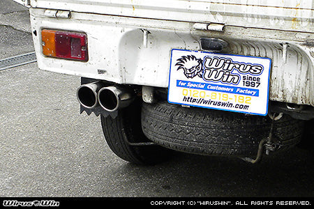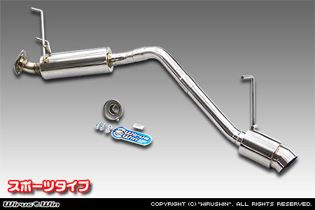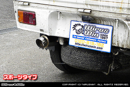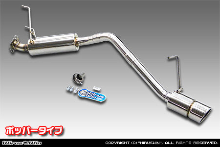
Daihatsu Hijet Exhaust Parts - S100, S110 Models - 1994-1998
Exhaust parts for 1994-1998 Daihatsu Hijet S100/S110 pickups and vans. Fitment follows the ENGINE code, full CHASSIS NO., body family, and turbo configuration. Pickups also route the pipe differently from vans.
Exhaust parts for 1994-1998 Daihatsu Hijet S100/S110 pickups and vans. Fitment follows the ENGINE code, the full CHASSIS NO., the body family, and the turbo configuration. Pickups also route the pipe differently from vans. Confirm these details before ordering.
Fitment follows the ENGINE code, full CHASSIS NO., body family, and turbo configuration.
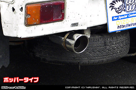
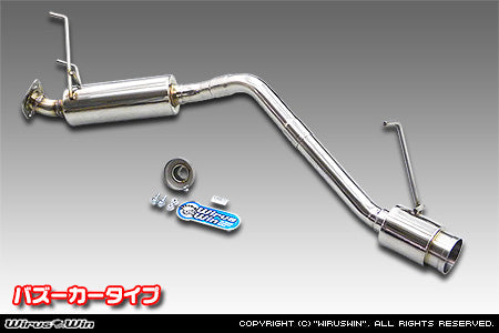
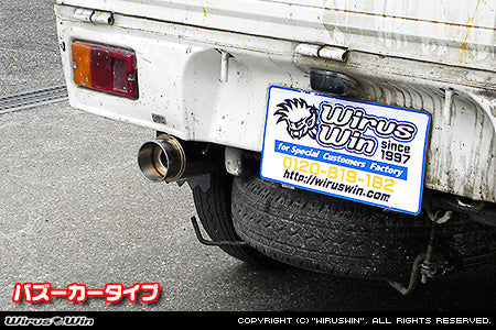
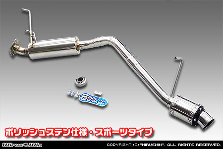
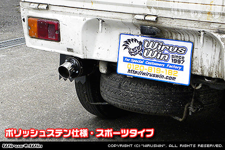
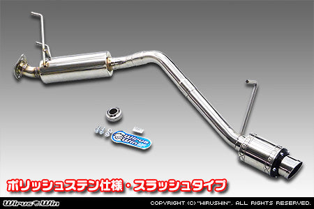
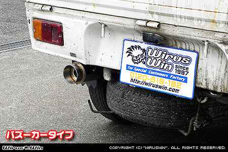
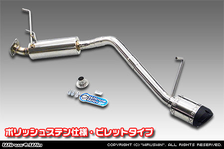
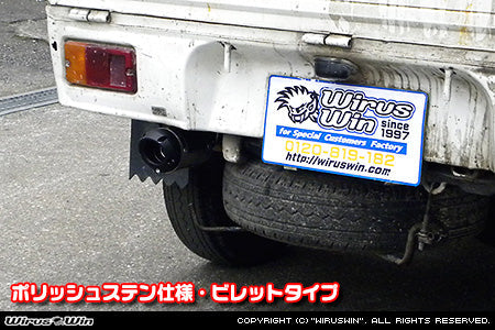
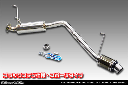
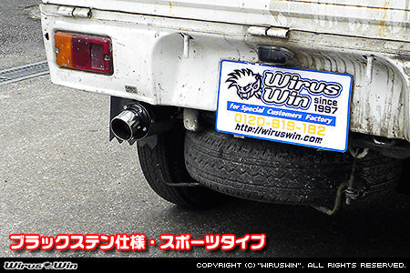
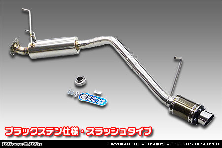
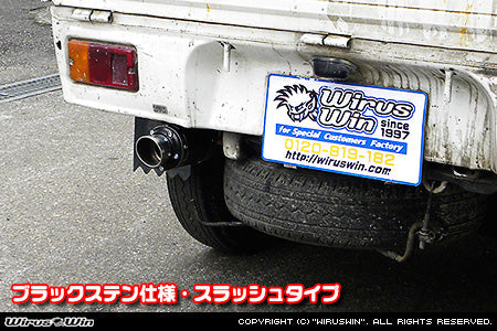
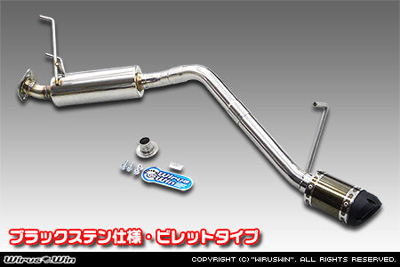
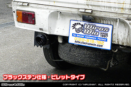
Exhaust manifold gaskets, single-use joint gaskets, muffler support cushions, and stainless mufflers for 1994-1998 Daihatsu Hijet S100/S110.
This collection covers exhaust manifold gaskets, the single-use pipe joint gaskets, muffler support cushions, plus stainless replacement mufflers for 1994-1998 Daihatsu Hijet S100/S110 pickups and vans.
EF-NS carbureted trucks use a different layout from the EF-ES and EF-TS fuel-injected trucks.
Confirm your ENGINE code and CHASSIS NO. before ordering.
Find Your Truck
The correct exhaust part follows the engine code, the body family, the drivetrain, and the turbo configuration. Model year alone does not confirm fitment.
Locate the vehicle identification plate, then read the complete CHASSIS NO. and ENGINE code before ordering.


| Fitment Check | What to Confirm | Parts Affected |
|---|---|---|
| Engine code | EF-NS is carbureted. EF-ES is fuel injected. EF-TS is turbocharged with fuel injection. | Exhaust manifold, front pipe, catalyst, sensors, heat shields, gaskets. |
| Body family | S100P and S110P identify pickups. S100V and S110V identify vans. | Pipe routing, joint arrangement, tailpipe shape, heat shields, under covers. |
| Drivetrain | S100 models are 2WD. S110 models are 4WD. | Brackets, stiffeners, vacuum routing on some 4WD models. |
| Turbo configuration | EF-TS is turbocharged. EF-NS and EF-ES are naturally aspirated. | Exhaust manifold No. 2, turbocharger, stays, heat insulator, oil and water pipes. |
| Sensor configuration | Every layout carries an exhaust-temperature sensor. EF-ES and EF-TS add an oxygen sensor with its own single-use gasket. | Front pipe, sensor boss, wiring connector, oxygen-sensor gasket. |
| Exhaust section | Front pipe, muffler assembly, or the joint between them. | Which assembly and which joint gasket you need. |
C and CT chassis codes. The factory manual covers S100C, S110C, S100CT plus S110CT alongside the P and V codes. The exhaust chapter labels its layout drawings pickup and van only. It gives no separate exhaust layout, part list or specification for the C or CT codes, so a part listed for a P-series truck is not automatically proven to fit one. Add your full CHASSIS NO. at checkout and we will check the specific part before shipping.
Choose Your Parts
Each category below is matched to a different part of the system. Confirm the fitment points in the right-hand column against your own truck before ordering.
| Category | What You Get | Fitment |
|---|---|---|
| Exhaust manifold gaskets | Engine-specific gaskets that seal the exhaust manifold to the cylinder head. | Match the engine code. EF-TS uses turbo-specific manifold sections. |
| Exhaust pipe joint gaskets | The two single-use gaskets at the front-pipe inlet joint and at the front pipe to muffler joint. | Match the engine code and the pickup or van layout. |
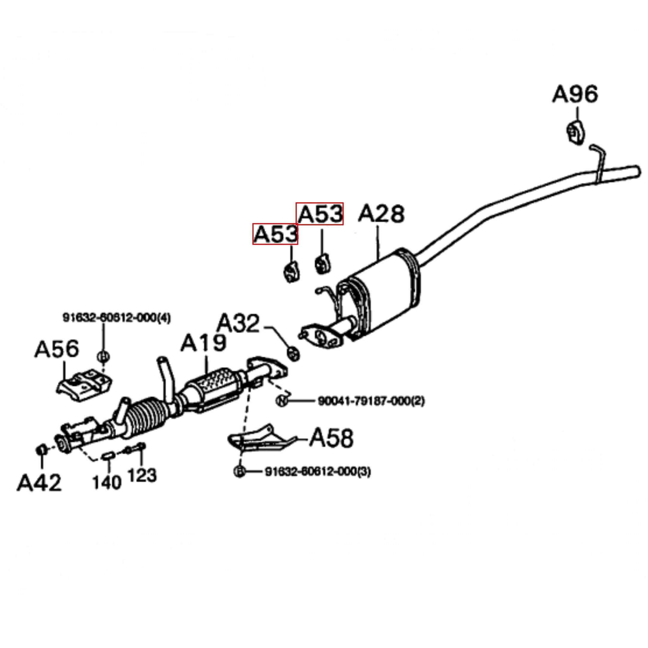
| Muffler support cushions | Rubber supports that suspend the muffler assembly from the body. | Match the body family and exhaust layout. Confirm against the product listing. |
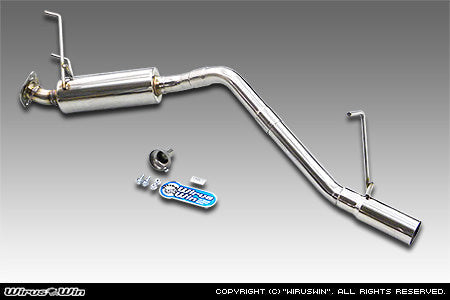
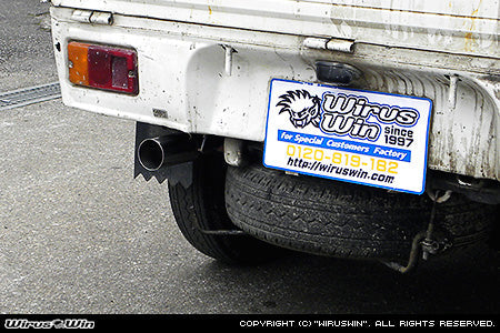
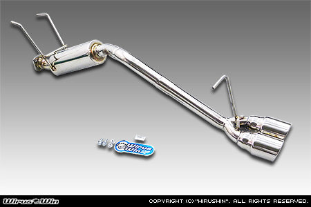
| Replacement mufflers | Stainless mufflers in polished or black finishes. Shapes and outlet styles vary by listing. | Check the inlet size, body clearance, and whether the listing is bolt-on or requires fabrication. |
| Oiwa Growler exhaust | An Oiwa Garage replacement for the factory muffler assembly, made in the USA from TIG-welded stainless steel at approximately seven pounds. | Confirm the body family and exhaust layout against the product listing. |
Which Exhaust Part Do You Need?
Start from something you have confirmed, not from a symptom on its own. Work through the troubleshooting section first, then use this table.
| Confirmed Finding | Typical Part Needed |
|---|---|
| Leak confirmed at the manifold-to-cylinder-head joint | The correct exhaust manifold gasket for your engine code. |
| Leak confirmed at an exhaust-pipe joint | The correct single-use exhaust joint gasket for that joint. |
| Muffler shell perforated, seam failed, or an internal baffle confirmed loose | Muffler assembly or a replacement exhaust. |
| Rubber support split, stretched, or no longer holding the exhaust correctly | The correct muffler support cushion. |
| Oxygen-sensor failure confirmed after the factory diagnostic sequence | Oxygen sensor with a new single-use gasket. |
| Exhaust-temperature sensor or warning-circuit fault confirmed by test | Whichever component the diagnostic proved faulty. |
A ticking noise, a rattle, an exhaust smell, an illuminated warning lamp or a stored code 21 is a reason to inspect. None of them identifies a failed part on its own.
Inspection & Service Intervals
The factory sets inspection intervals rather than automatic replacement dates. Commercial-use trucks are inspected more often than private-use trucks.
| Inspection Item | Private Use | Commercial Use | Application or Note |
|---|---|---|---|
| Exhaust condition | 6, 12, and 24 months | 1, 3, and 12 months | Includes the factory idle-emissions inspection. |
| Catalyst mounting: looseness or damage | 12 and 24 months | 3 and 12 months | Applies to the catalyst-type exhaust-gas reduction device. |
| Secondary-air system operation | Not applicable | Not applicable | The factory schedule lists this item, then marks it not applicable to these vehicles. |
| EGR system operation | 12 and 24 months | 3 and 12 months | EF-NS only. Not required on fuel-injected models. |
| Deceleration emission-control operation | 12 and 24 months | 3 and 12 months | EF-NS only. Not required on fuel-injected models. |
| Emission-control piping: damage or loose installation | 12 and 24 months | 3 and 12 months | Refers to related emission-control piping, not the main exhaust pipe. |
| Heat-shield mounting: looseness or damage | 12 and 24 months | 3 and 12 months | Inspect the shields together with their fasteners. |
| Exhaust pipe and muffler mounting: looseness or damage | 12 and 24 months | 3 and 12 months | Covers joints, supports, and mounting condition. |
| Muffler operation | 24 months only | 12 months only | Checked at the longer interval only. |
| Cylinder head and manifold fastener tightness | Not scheduled | 12 months | Commercial-use inspection. Check with the engine cold. |
The exhaust-condition inspection includes an idle-emissions check; the CO and HC limits are in Specifications. On EF-ES and EF-TS engines the factory measures emissions straight after the oxygen-sensor feedback test, because the sensor cools while you work.
Exhaust System Layouts
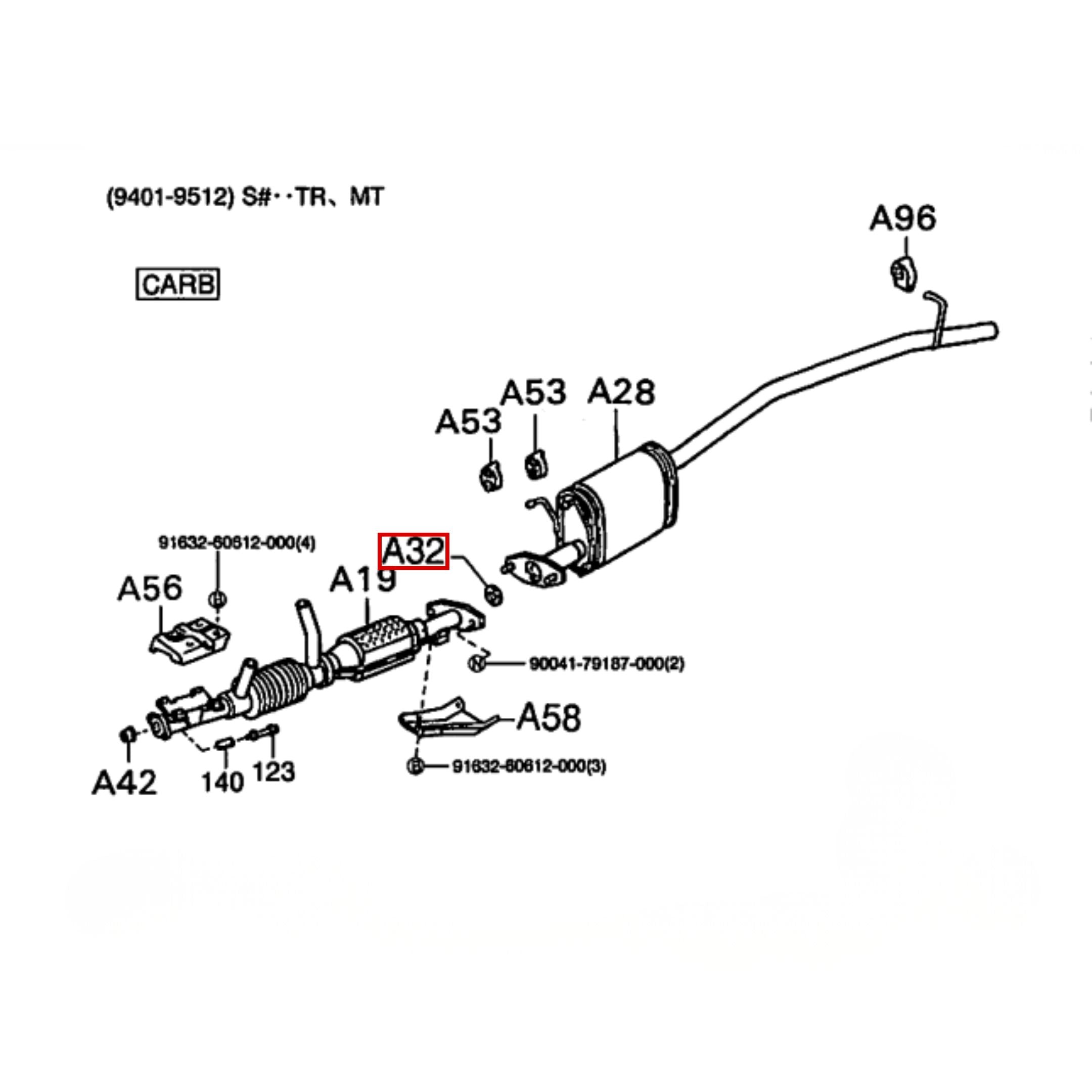
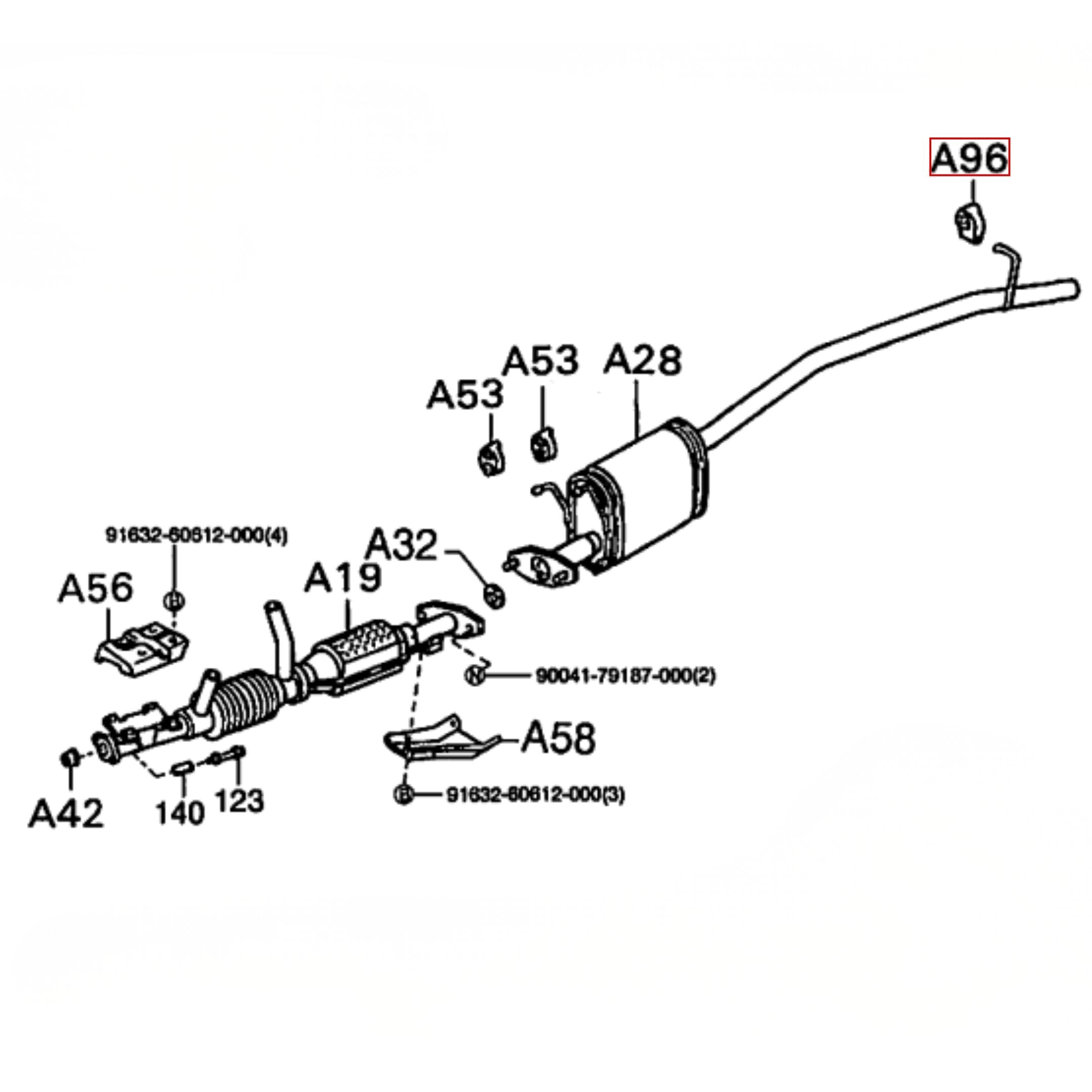
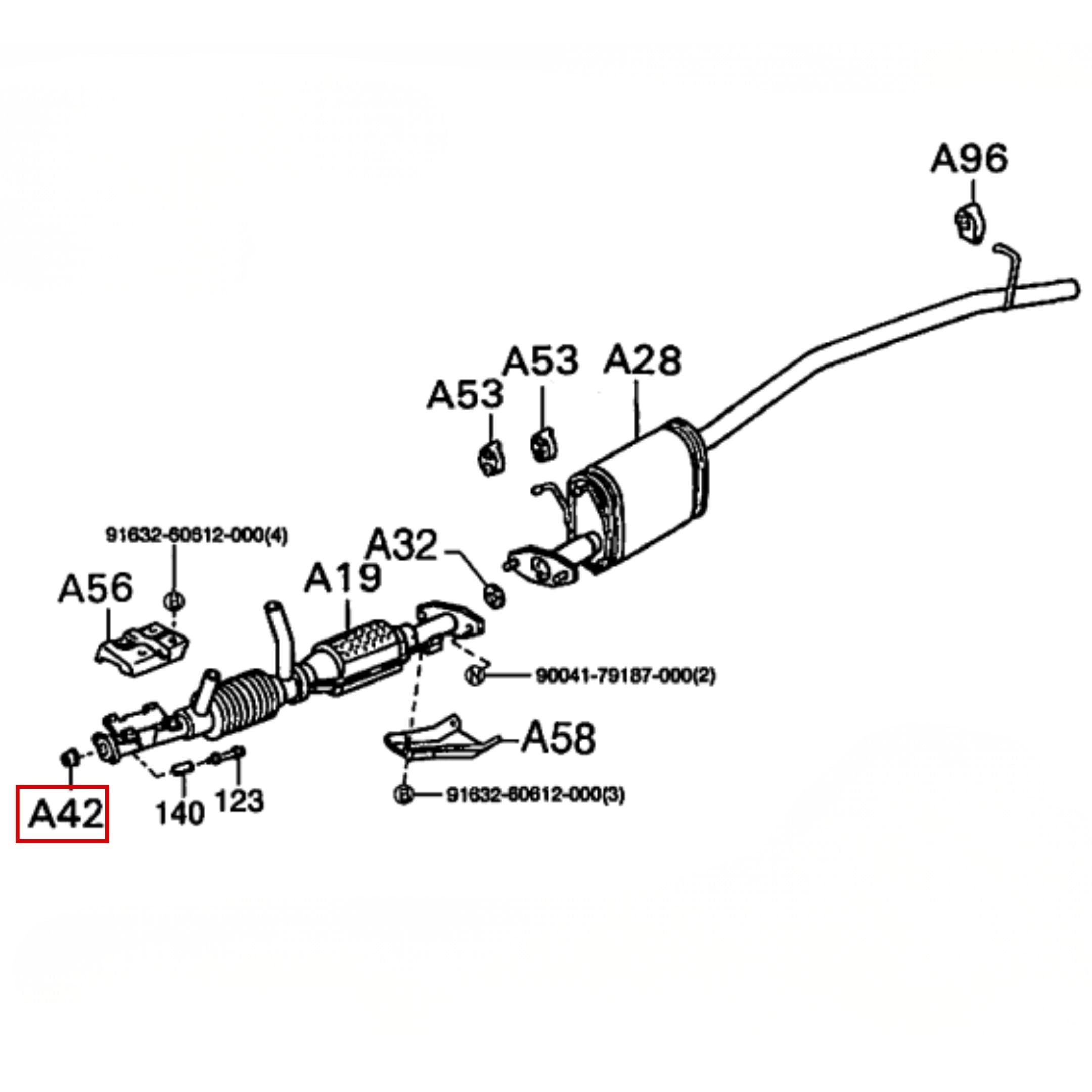
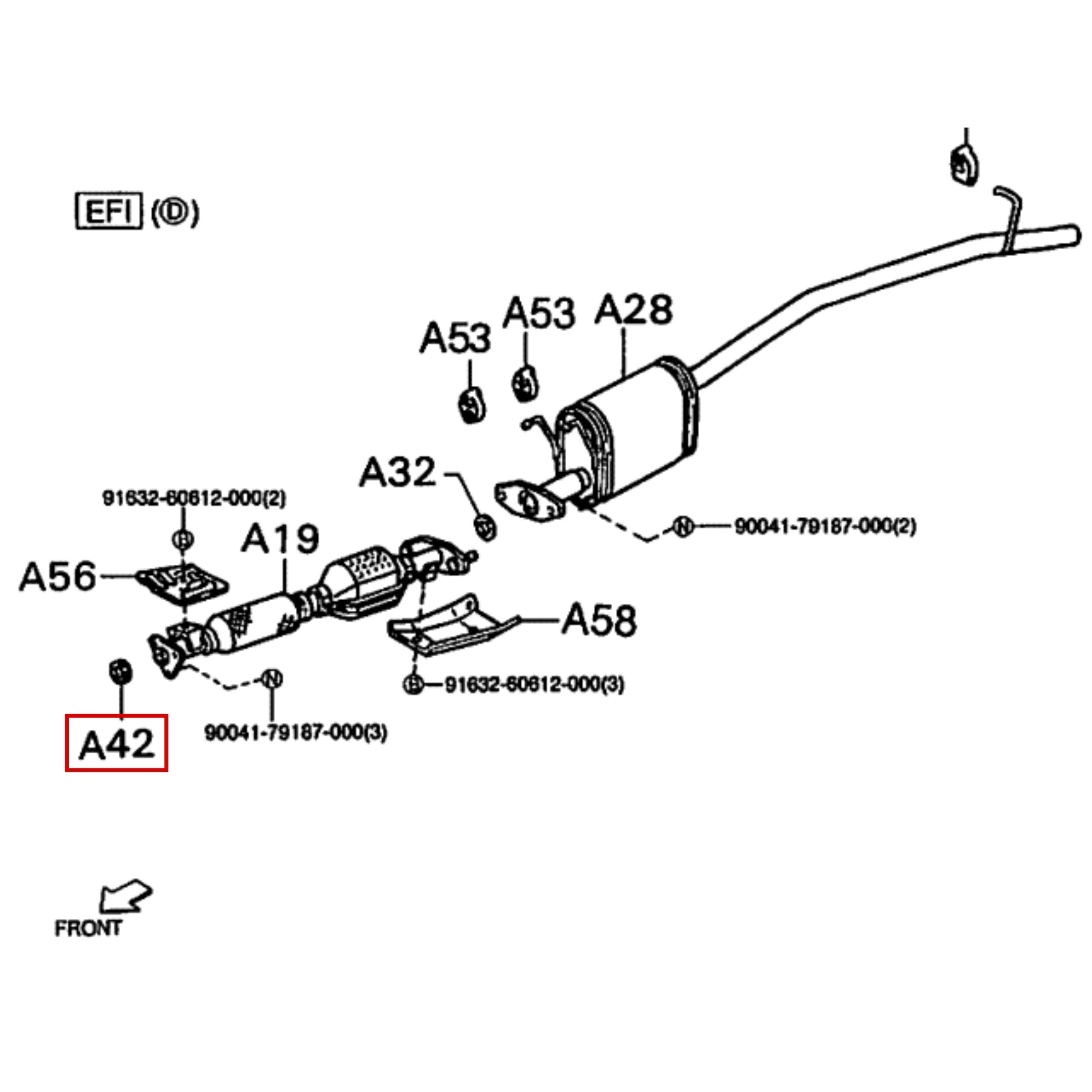
The factory draws one exhaust layout for the carbureted engine and another for the fuel-injected engines. Each drawing shows the pickup above the van, because the two body families route the pipe differently.


Shared by every layout
| Factory No. | Component | What It Is | Application |
|---|---|---|---|
| 6 | Front Exhaust-Pipe Assembly | The pipe between the engine outlet and the muffler. The catalytic converter is built into this assembly. | All layouts. Match the engine and body family. |
| 11 | Exhaust Muffler Assembly | The muffler and tailpipe supplied as one assembly. | All layouts. Pickup and van routing differs. |
| 8 | Front Joint Gasket | Single-use gasket at the front exhaust-pipe connection. | All layouts. Match the engine. |
| 7 | Center Joint Gasket | Single-use gasket between the front pipe and the muffler assembly. | All layouts. Match the exhaust configuration. |
| 9 | Heat Insulator No. 1 | Heat shield fitted over the front section of the exhaust pipe. | All layouts. Shape varies by application. |
| 5 | Heat Insulator No. 3 | Longer heat shield fitted along the exhaust pipe. | All layouts. Shape varies by application. |
| 1 | Engine-Side Under Cover | Protective panel beneath the engine and exhaust area. | All layouts. Pickup and van versions differ. |
| 12 | Muffler Support | Rubber support that suspends the muffler assembly. | All layouts. |
| 10 | Exhaust-Temperature Sensor | Monitors catalyst temperature for the overheat warning system. | All layouts. |
| 2 | Exhaust-Temperature Sensor Connector | Connects the sensor to the warning circuit. | All layouts. |
Varies by engine
| Factory No. | Component | What It Is | Application |
|---|---|---|---|
| 3 | Oxygen Sensor | Provides exhaust feedback for electronic air-fuel control. | EF-ES and EF-TS only. |
| 4 | Oxygen-Sensor Gasket | Single-use gasket installed with the oxygen sensor. | EF-ES and EF-TS only. |
| 3 and 4 | Air-Inlet Ducts | Two flexible ducts routed near the front exhaust pipe. | EF-NS only. |
| Not numbered here | Exhaust Manifold Gasket | Seals the exhaust manifold to the cylinder head. | Engine-specific. The factory does not mark this gasket as single-use. |
| Shown separately | Turbo Exhaust Hardware | EF-TS manifold sections, turbocharger connections, stays, heat shields, gaskets. | EF-TS only. |
The factory treats the front pipe and the muffler as complete replacement assemblies. It gives removal and installation procedures for them rather than overhaul instructions. A torque wrench is the only tool the section lists.
Turbo & Emissions Hardware
EF-TS Turbo Exhaust Hardware
On EF-TS models the exhaust passes through the turbocharger before it reaches the front pipe. That adds supports, heat shielding, service pipes and sealing points the naturally aspirated engines never use.
| Part | What It Does | Service Note |
|---|---|---|
| Exhaust Manifold No. 2 | Connects the main exhaust manifold to the turbocharger. | EF-TS only. Install a new gasket whenever the joint is opened. |
| Turbocharger Assembly | Uses exhaust flow to create boost before the gas enters the front pipe. | Install a new gasket during reassembly. |
| Exhaust-Manifold Stay | Supports exhaust manifold No. 2. | Fastener torque varies by bolt location. |
| Turbocharger Stay | Supports the turbocharger against the engine. | Fastener torque varies by bolt location. |
| Turbocharger Heat Insulator | Shields nearby components from turbocharger heat. | Separate from exhaust-pipe heat insulators No. 1 and No. 3. |
| Turbo Oil and Water Pipes | Feed oil and coolant to the turbocharger, then return them to the engine. | The oil-inlet, oil-outlet and water-pipe gaskets are all single-use. |
| Front Exhaust-Pipe Connection | Connects the turbocharger outlet to the rest of the exhaust system. | Reinstall both pipe heat shields. |
| Powertrain Stiffener | Structural brace fitted to 4WD automatic models. | Not an exhaust component. Removed only when the job continues into turbocharger removal. |
Catalyst and Sensor Configuration
| Engine | Catalyst | Sensors Fitted |
|---|---|---|
| EF-NS | Monolith built into the front exhaust-pipe assembly | Exhaust-temperature sensor only. |
| EF-ES | Monolith built into the front exhaust-pipe assembly | Exhaust-temperature sensor plus an oxygen sensor with a single-use gasket. |
| EF-TS | Monolith built into the front exhaust-pipe assembly | Exhaust-temperature sensor plus an oxygen sensor with a single-use gasket. |
Because the catalyst is part of the front pipe rather than a separate canister, the front pipe has to match the engine code.
Troubleshooting
Work down the inspection column before you order anything. Each of these points at more than one cause, so the aim is to find the joint or component at fault rather than to guess at a part.
| What You Notice | What to Inspect, in Order |
|---|---|
| Ticking on a cold start that fades as the engine warms | The manifold-to-cylinder-head joint, for soot, loose fasteners, then gasket damage. |
| Blowing or hissing under load | The front-pipe inlet joint, then the front pipe to muffler joint, for soot or movement. |
| Exhaust smell or visible soot near the cab | The manifold, the front-pipe joints, then the nearby pipe seams. |
| Metallic rattle that changes with engine speed | Heat insulators, the engine under cover, their fasteners, then component clearance. |
| Knock or clunk over bumps | The rubber muffler support, for cracks, stretching, or a low-hanging muffler. |
| Muffler louder than it was, or rust at a seam | The muffler body, the welds, the tailpipe, then the inlet connection. |
| Warning lamp stays on after the engine starts | The sensor connector, the harness, the exhaust-temperature relay, then the warning circuit. |
| Warning lamp comes on while driving | Stop when it is safe. Check for catalyst overheating, then work through the warning-system test below. |
| Warning lamp does not illuminate with the ignition on | The bulb, the relay, the wiring, then the sensor circuit. |
| Diagnostic code 21 is stored | The oxygen-sensor signal, then the harness between the sensor and the ECU. Follow the factory order below. |
Oxygen Sensor and Code 21
Code 21 does not prove the oxygen sensor failed. It reports a fault in the oxygen-sensor signal circuit. This procedure applies to EF-ES and EF-TS engines.
- Diagnose any other stored codes first.
- Warm the oxygen sensor at 3,000 rpm for four minutes.
- Check VF feedback at 1,200 rpm or higher. The voltage must switch between 0 and 5 V at least eight times in 10 seconds.
- If VF fails, test the oxygen-sensor output directly at 2,000 rpm or higher. It must switch between approximately 0.2 and 1.0 V at least eight times in 10 seconds.
- Inspect the sensor wiring, the VF and ECU wiring, then the connectors.
- If the wiring is sound, test the pressure sensor, the fuel pressure, the injectors, then the spark plugs.
- Replace the oxygen sensor only once the remaining checks have passed.
The oxygen-sensor signal is weak, so the factory reads VF output through the diagnostic connector before it tests the sensor directly. Direct testing needs the specified special service tool connection.
Code 21 only stores under specific conditions: the engine is warm, engine speed stays above 3,000 rpm, the power switch is ON, and the sensor never reports a rich mixture.
Exhaust-Overheat Warning System
All three engines use this system. It is an exhaust-temperature sensor at the catalyst, a relay, and a warning lamp in the cluster. An illuminated lamp means the circuit is reporting a fault, which may be a genuine overheat or a sensor, relay or wiring problem.


- Turn the ignition ON without starting the engine. The lamp should illuminate.
- Start the engine. The lamp should go out.
- Measure continuity between the sensor terminal and the sensor body. Resistance must be 3 Ω or less.
- Inspect the sensor mounting bolt for looseness, the harness for damage, then the connector for secure engagement. Repair any fault found.
- With the engine running, disconnect the sensor connector. The lamp should illuminate, which confirms the warning circuit responds.
If the warning returns after the electrical checks pass, diagnose the fuel-control system before condemning the catalyst. The factory relies on deceleration fuel cut to protect the catalyst from overheating.
Installation & Single-Use Parts
Order the single-use gaskets with the part itself. Every joint below has to be sealed with a new gasket once it has been opened.
| Service Operation | Parts That Must Be Replaced |
|---|---|
| Disconnecting the front exhaust pipe at its inlet joint | Front exhaust joint gasket. Clean both mating faces before fitting it. |
| Separating the muffler assembly from the front pipe | Center exhaust joint gasket. |
| Removing the oxygen sensor, EF-ES and EF-TS | Oxygen-sensor gasket. |
| Removing the turbocharger assembly, EF-TS | Turbocharger assembly gasket. |
| Removing exhaust manifold No. 2, EF-TS | Exhaust manifold No. 2 gasket. |
| Disconnecting a turbo oil or water pipe, EF-TS | A new gasket at each opened connection: oil inlet, oil outlet, water pipe No. 1. |
Before removal
- Allow the exhaust to cool completely before removing the oxygen sensor or the exhaust-temperature sensor.
- Do not reuse the oxygen-sensor gasket or either exhaust-pipe gasket.
- Clean the pipe-joint mating surfaces before the new gaskets go on.
Reassembly
Fit new exhaust-pipe gaskets at both joints. EF-ES and EF-TS models also need a new oxygen-sensor gasket. Refit both pipe heat shields, reconnect the sensor wiring securely, then check the rubber muffler support while the system is still apart.
On EF-NS models the two air ducts have a marked side, and it faces a specific way.

EF-TS front-pipe removal
- Remove the RH engine under cover and the LH engine-side under cover.
- Remove air-cleaner hose No. 1 with the air-cleaner cap assembly.
- Remove air hose No. 2.
- Let the exhaust cool, then remove the oxygen sensor.
- Remove exhaust-pipe heat insulators No. 1 and No. 3.
- Remove the front exhaust-pipe assembly.
4WD automatic models. The powertrain stiffener comes out at the next step, and only when the job continues into turbocharger removal. It is not required to get the front pipe off.
The numbered labels in the layout drawings identify components. They are not a removal order, so follow the written procedure for sequence.
Specifications
Every figure below is a factory value. Torque is printed in kgf·cm; the N·m and ft-lb columns are calculated conversions. Use the full range rather than its midpoint.
Catalyst and sensors
| Item | Engine | Factory Value |
|---|---|---|
| Catalyst volume, monolith type | EF-NS | 0.7 L |
| Catalyst volume, monolith type | EF-ES and EF-TS | 0.5 L |
| Exhaust-temperature sensor continuity, terminal to sensor body | All engines | 3 Ω or less |
| Oxygen-sensor VF feedback, 1,200 rpm or higher, engine warm | EF-ES and EF-TS | 0 to 5 V, at least 8 switches in 10 seconds |
| Oxygen-sensor output measured directly, 2,000 rpm or higher, engine warm | EF-ES and EF-TS | Approximately 0.2 to 1.0 V, at least 8 switches in 10 seconds |
| Idle emissions, CO | EF-NS | 1.0% to 2.5% |
| Idle emissions, CO | EF-ES and EF-TS | 1.5% or less |
| Idle emissions, HC | EF-NS | 900 ppm or less |
| Idle emissions, HC | EF-ES and EF-TS | 800 ppm or less |
Manifold limits
| Item | Engine | Factory Limit |
|---|---|---|
| Exhaust manifold warpage, cylinder head face | EF-ES | 0.10 mm |
| Exhaust manifold warpage, cylinder head face | EF-NS and EF-TS | 0.5 mm |
| Intake manifold warpage, cylinder head face | All engines | 0.10 mm |
Exhaust joints and sensors, torque
| Fastener or Joint | Application | kgf·cm | N·m | ft·lb |
|---|---|---|---|---|
| Exhaust manifold to cylinder head | EF-NS, EF-ES | 204–306 | 20.0–30.0 | 14.8–22.1 |
| Exhaust manifold to cylinder head | EF-TS | 250–350 | 24.5–34.3 | 18.1–25.3 |
| Front-pipe inlet joint FACTORY CONFLICT |
Master tightening table | 400–550 | 39.2–53.9 | 28.9–39.8 |
| Front-pipe inlet joint FACTORY CONFLICT |
Injected van drawing, engine and turbo procedures | 420–570 | 41.2–55.9 | 30.4–41.2 |
| Front pipe to muffler FACTORY CONFLICT |
Master tightening table, carbureted and injected pickup drawings | 420–570 | 41.2–55.9 | 30.4–41.2 |
| Front pipe to muffler FACTORY CONFLICT |
Injected van drawing | 400–550 | 39.2–53.9 | 28.9–39.8 |
| Oxygen sensor to exhaust pipe | EF-ES, EF-TS | 300–400 | 29.4–39.2 | 21.7–28.9 |
| Exhaust-temperature sensor to exhaust pipe | All engines | 350–450 | 34.3–44.1 | 25.3–32.5 |
Turbocharger, stays and EGR hardware, torque
| Fastener or Joint | Application | kgf·cm | N·m | ft·lb |
|---|---|---|---|---|
| Exhaust manifold No. 2 to stay | EF-TS | 156–234 | 15.3–22.9 | 11.3–16.9 |
| Turbocharger to exhaust manifold | EF-TS | 204–306 | 20.0–30.0 | 14.8–22.1 |
| Turbocharger to exhaust manifold No. 2 | EF-TS | 204–306 | 20.0–30.0 | 14.8–22.1 |
| Turbocharger and manifold stays, Bolt A | EF-TS | 600 ± 100 | 49.0–68.6 | 36.2–50.6 |
| Turbocharger and manifold stays, Bolt B | EF-TS | 375 ± 75 | 29.4–44.1 | 21.7–32.5 |
| Turbocharger and manifold stays, Bolt C | EF-TS | 400 ± 80 | 31.4–47.1 | 23.1–34.7 |
| EGR valve to intake manifold, master tightening table | EF-NS | 104–156 | 10.2–15.3 | 7.5–11.3 |
| EGR valve to intake manifold, installation procedure | EF-NS | 156–234 | 15.3–22.9 | 11.3–16.9 |
Factory Notes
Three specifications are printed with conflicting factory values. None of the conflicting printings is marked as superseding the other, so Specifications preserves the values and this section explains where each one appears.
| Specification | Printed as | Where it appears |
|---|---|---|
| Front-pipe inlet joint | 400–550 kgf·cm | Master tightening table |
| Front-pipe inlet joint | 420–570 kgf·cm | Injected van drawing, plus the engine and turbo procedures |
| Front pipe to muffler | 420–570 kgf·cm | Master tightening table, carbureted and injected pickup drawings |
| Front pipe to muffler | 400–550 kgf·cm | Injected van drawing |
| EGR valve to intake manifold | 104–156 kgf·cm | Master tightening table |
| EGR valve to intake manifold | 156–234 kgf·cm | Installation procedure |
The same pair of ranges runs through both pipe joints; the injected van drawing swaps which joint gets which, and the engine and turbo procedures print the higher range at the inlet. Daihatsu never states which printing wins, so neither is treated here as authoritative over the other.
The periodic inspection schedule rounds the exhaust-manifold fastener check to 200–300 kgf·cm. That is the inspection figure, not a second assembly specification.
Where can I buy Daihatsu Hijet exhaust parts in the United States?
Oiwa Garage ships Daihatsu Hijet exhaust parts from our California warehouse. Availability varies by part, so check the individual listing. Not sure you selected the right parts? Add your full CHASSIS NO. and ENGINE code at checkout and we will verify fitment before shipping.
Our 100% Fitment Guarantee
Add your VIN or chassis number at checkout and we verify the fitment of every part in your order before anything ships. We check your full chassis code and engine code, plus the body family, drivetrain, turbo configuration, sensor configuration or exhaust section where the part needs them. If anything does not match your truck, we contact you before dispatch. If something arrives wrong, we exchange it or refund you in full. No hassle, no runaround.
Contact Our Fitment Specialistsor text us directly at 562-661-8862
Fitment verified by the Kei Truck specialists at Oiwa Garage · Collection description updated August 2026.