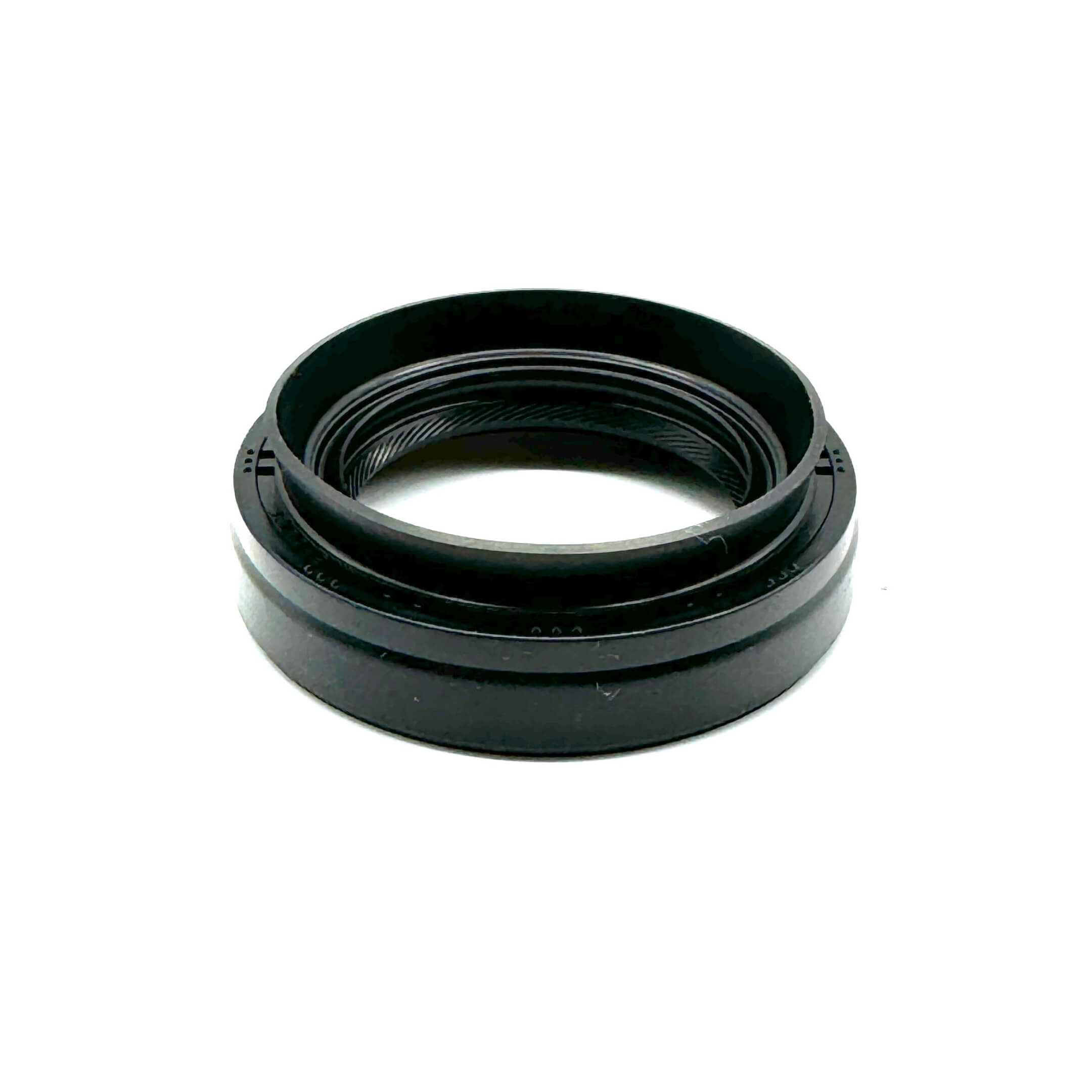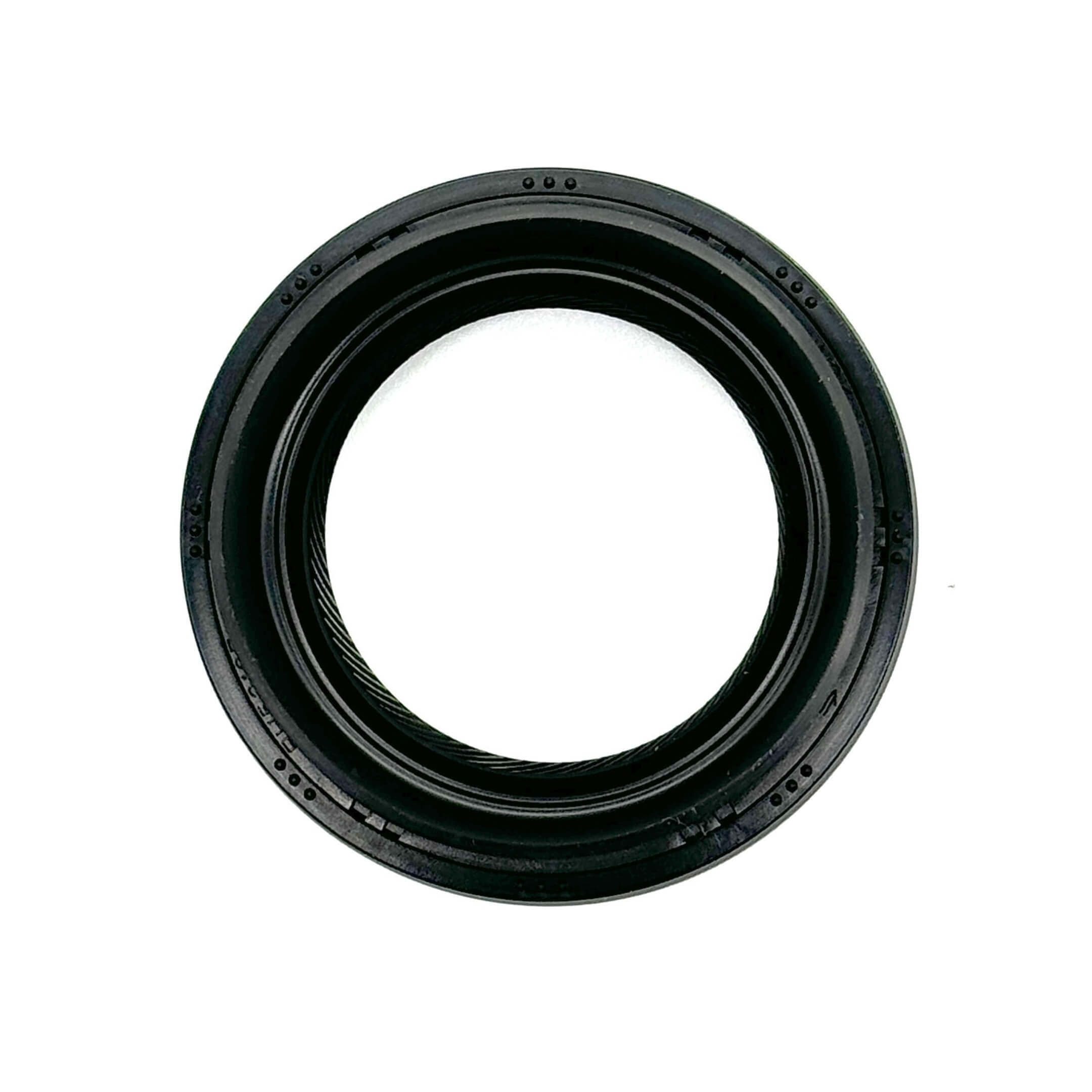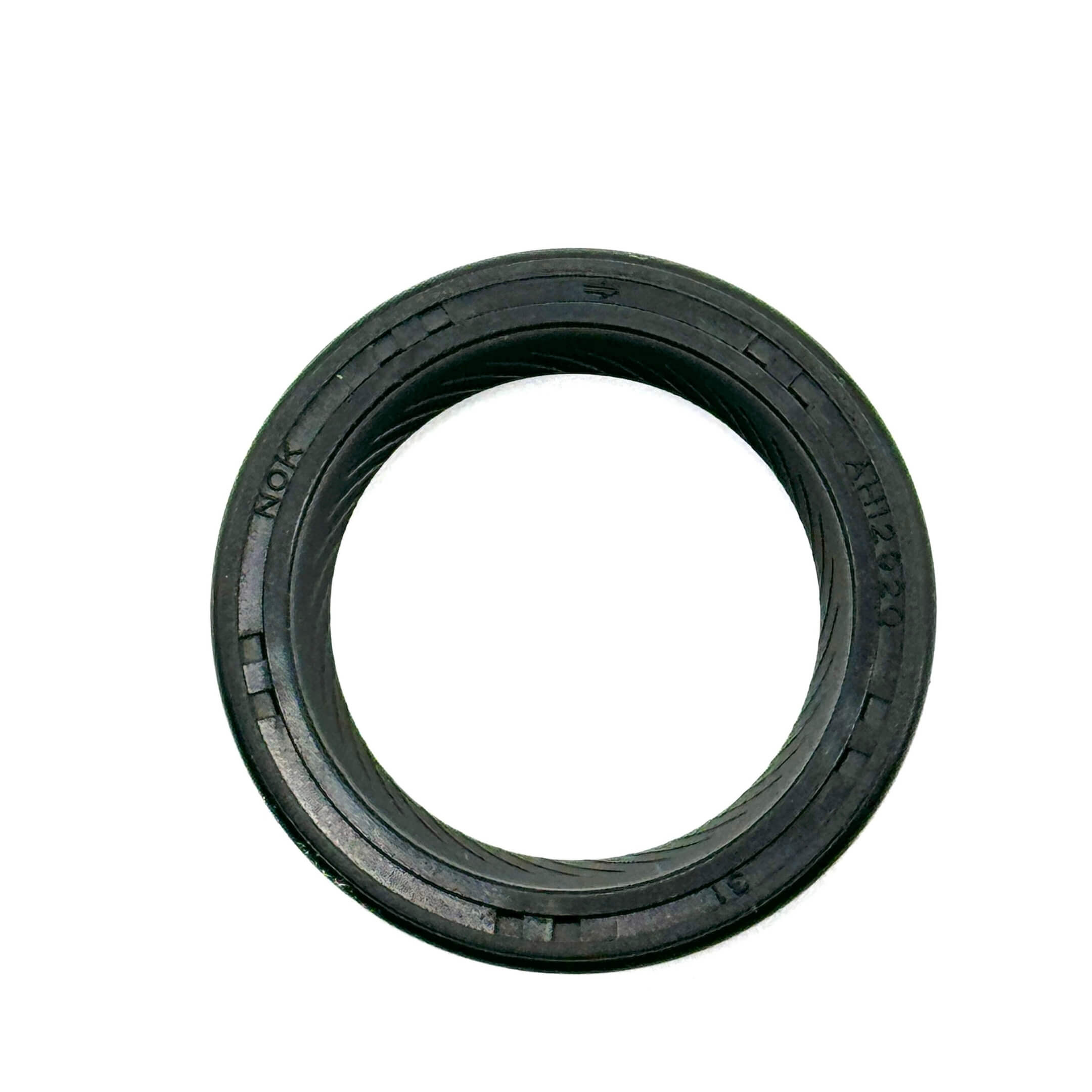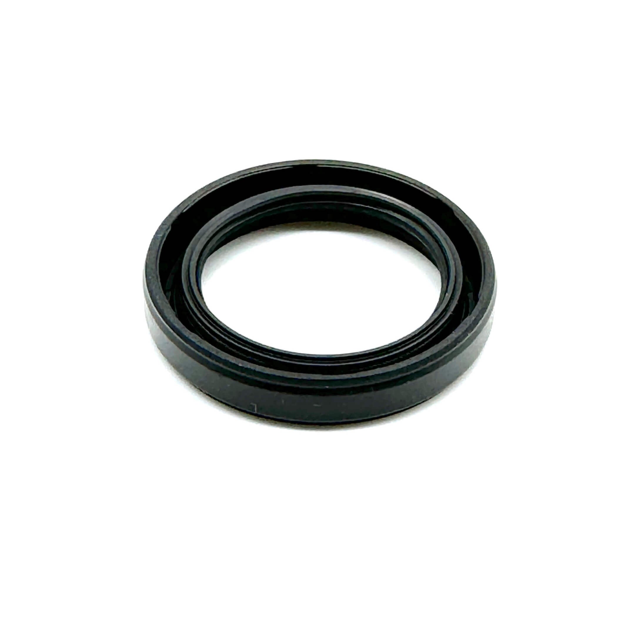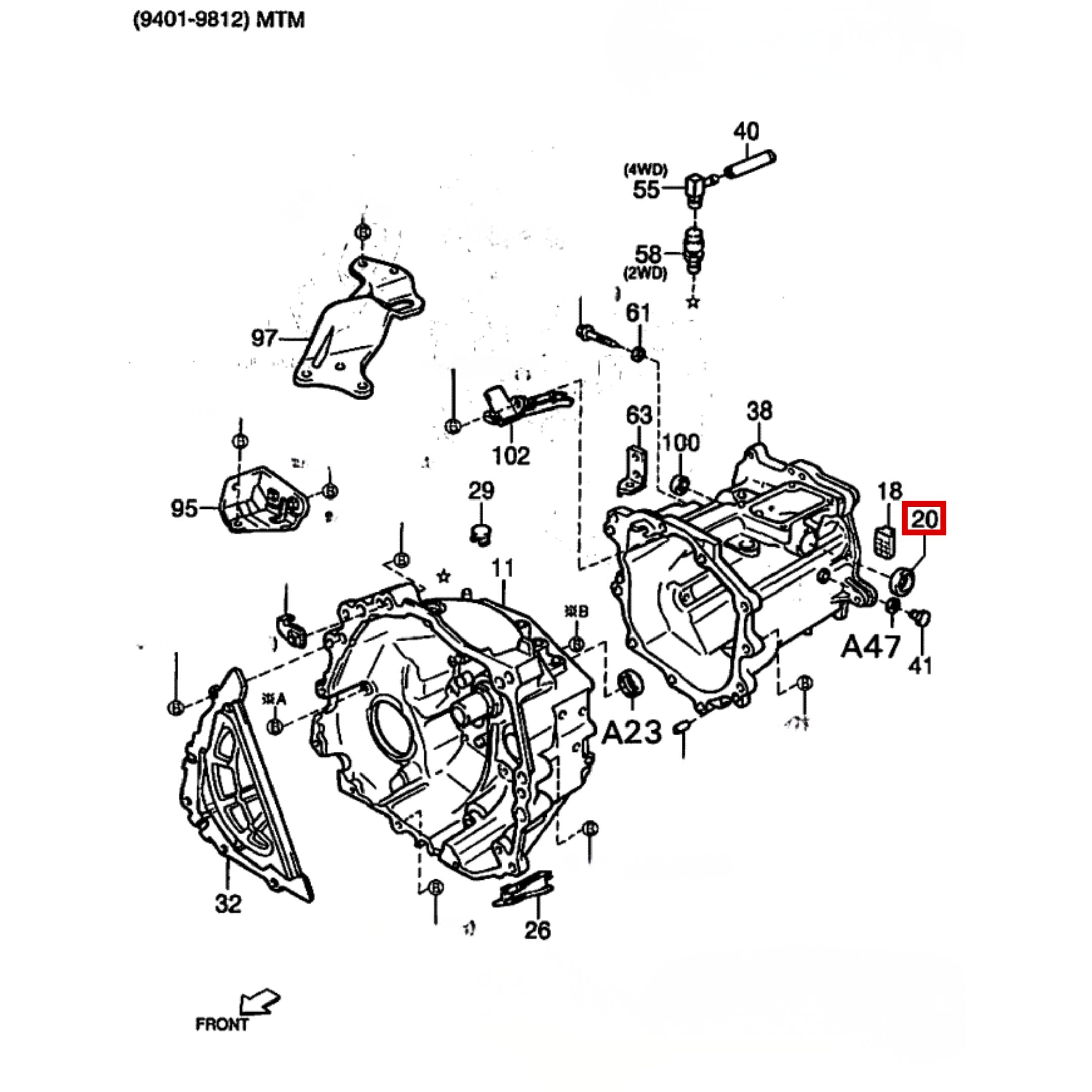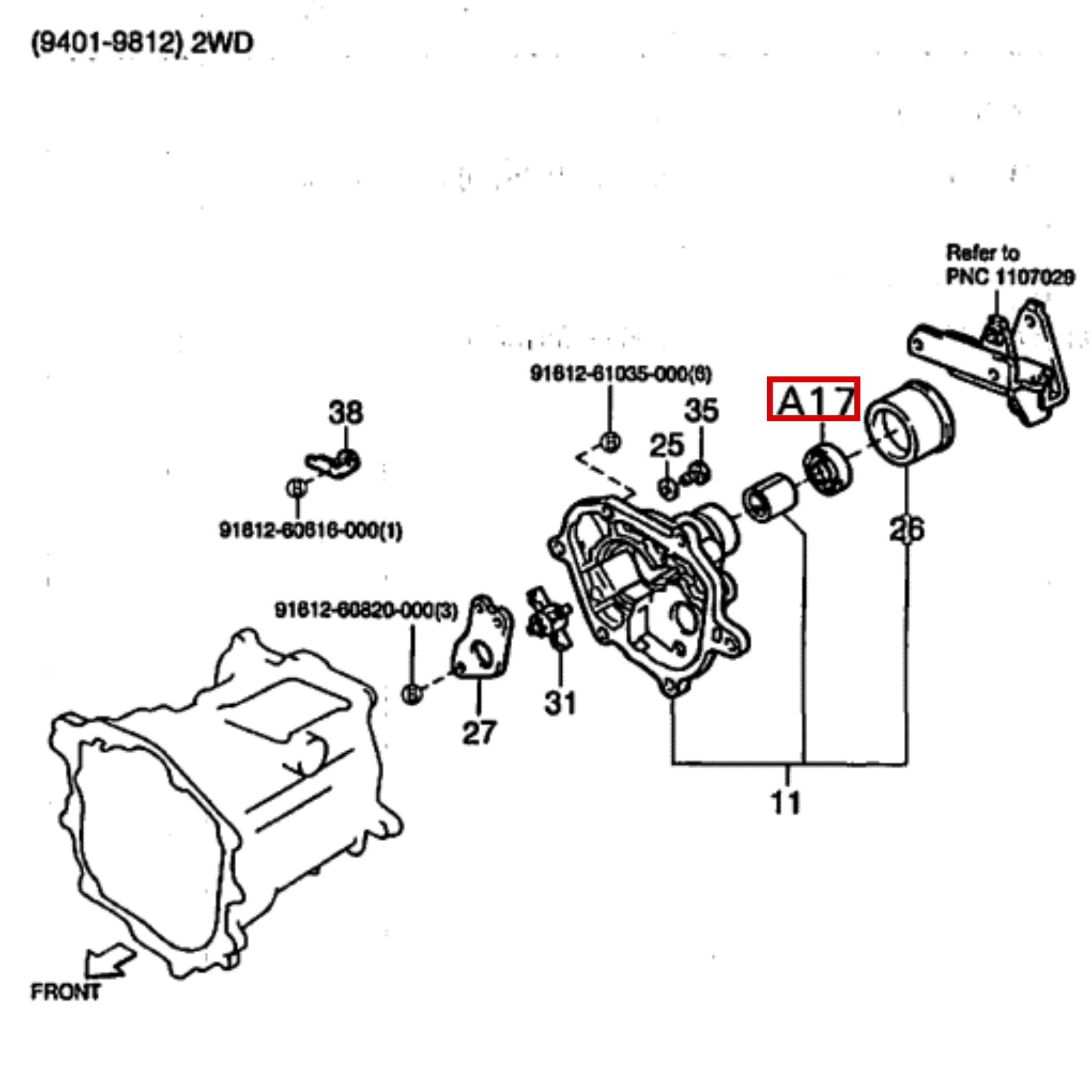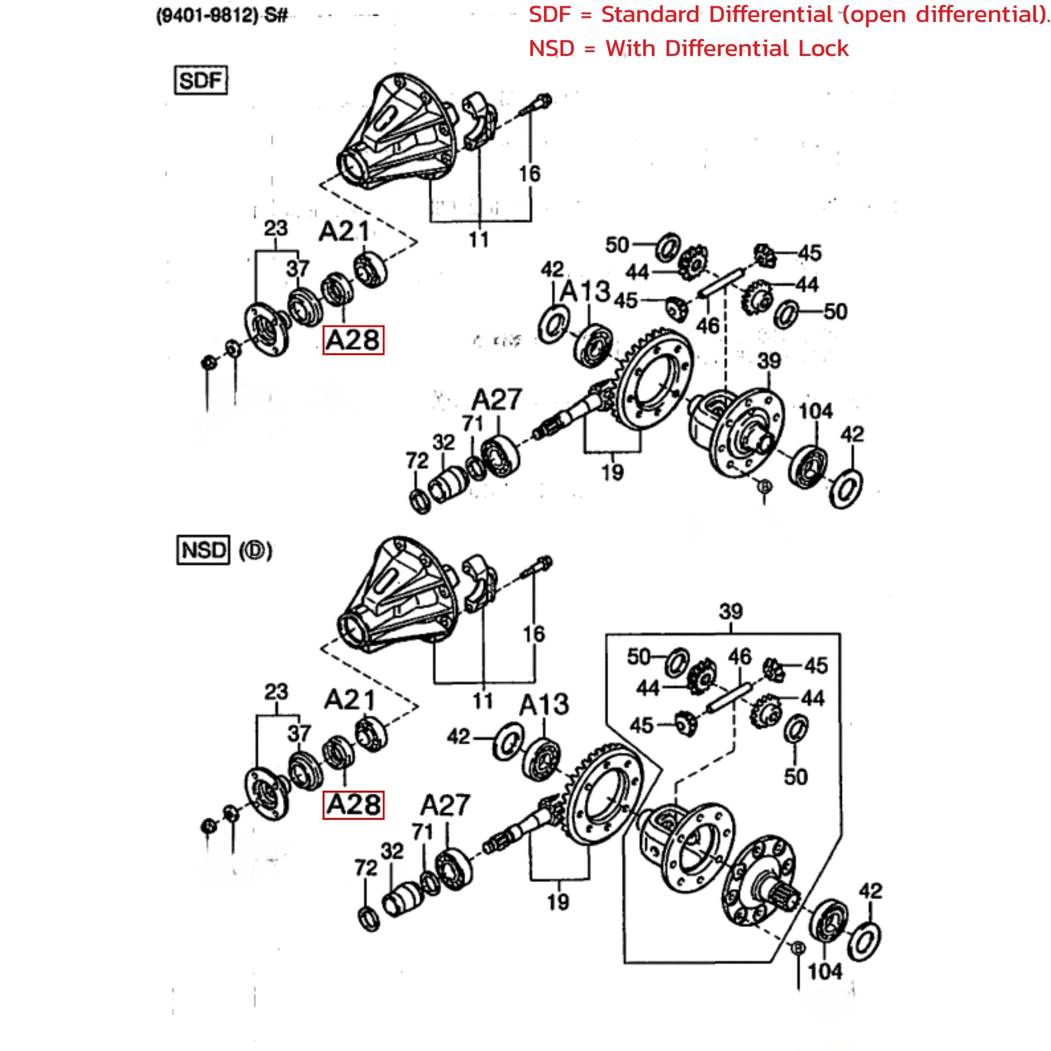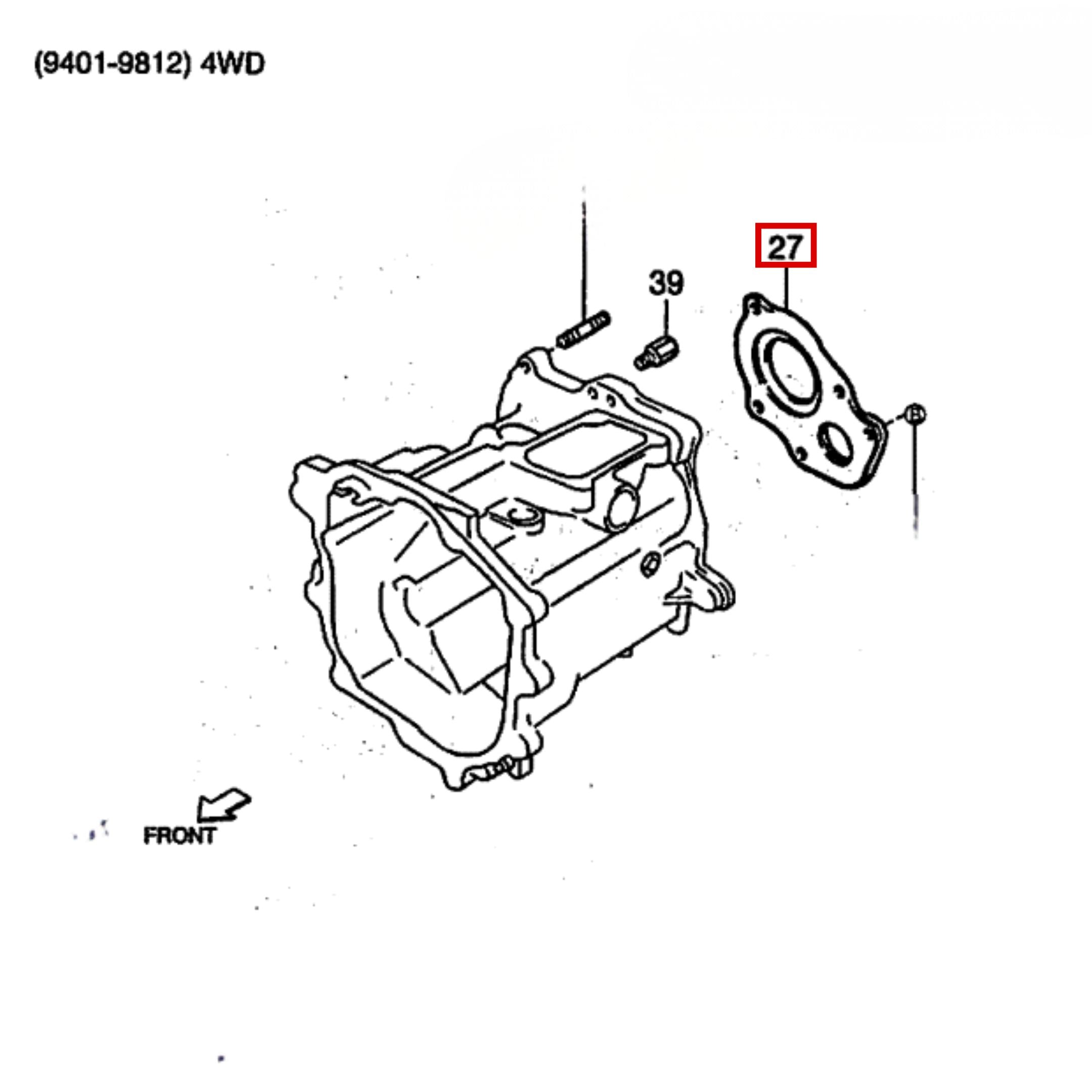
Daihatsu Hijet Steering Parts - S100, S110 Models - 1994-1998
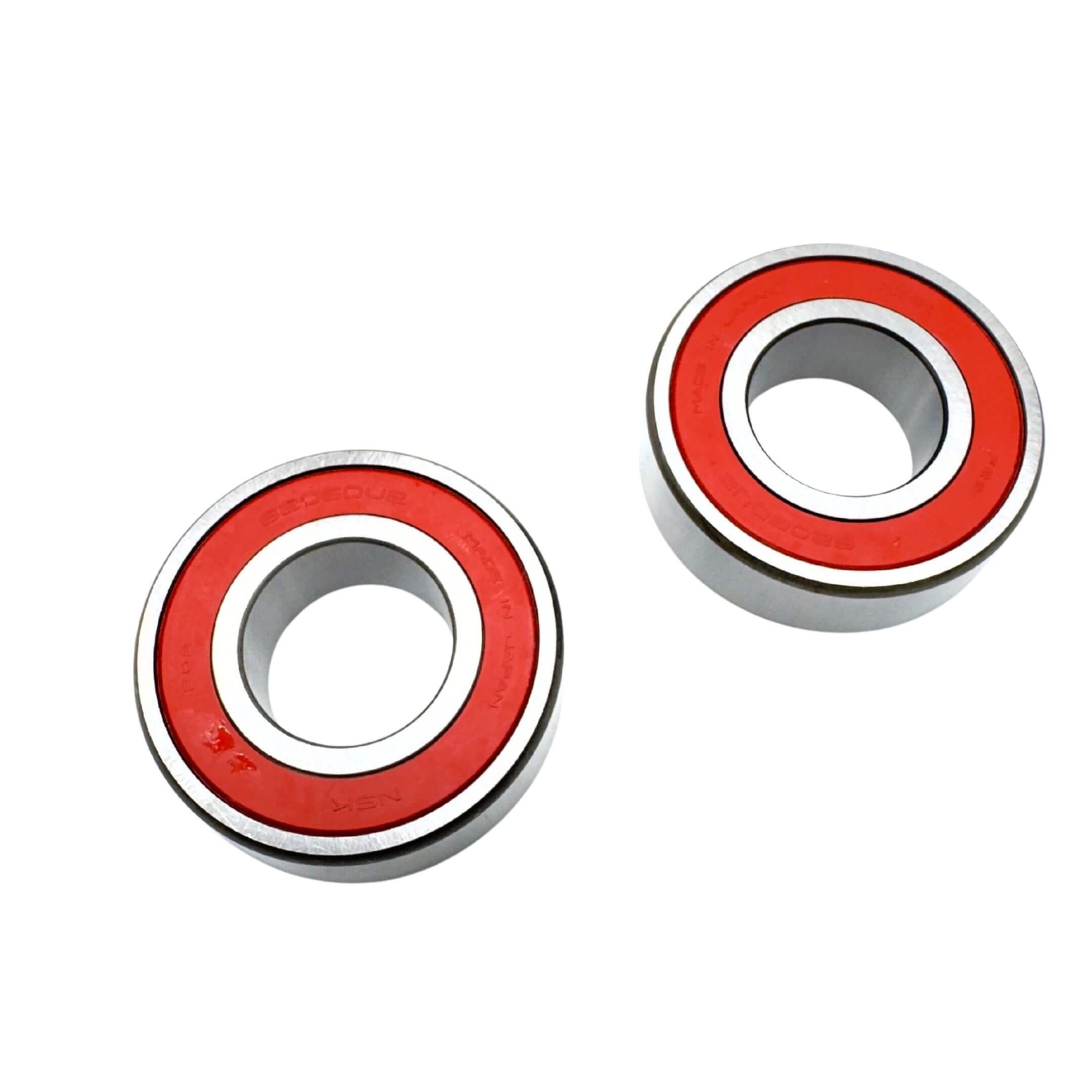
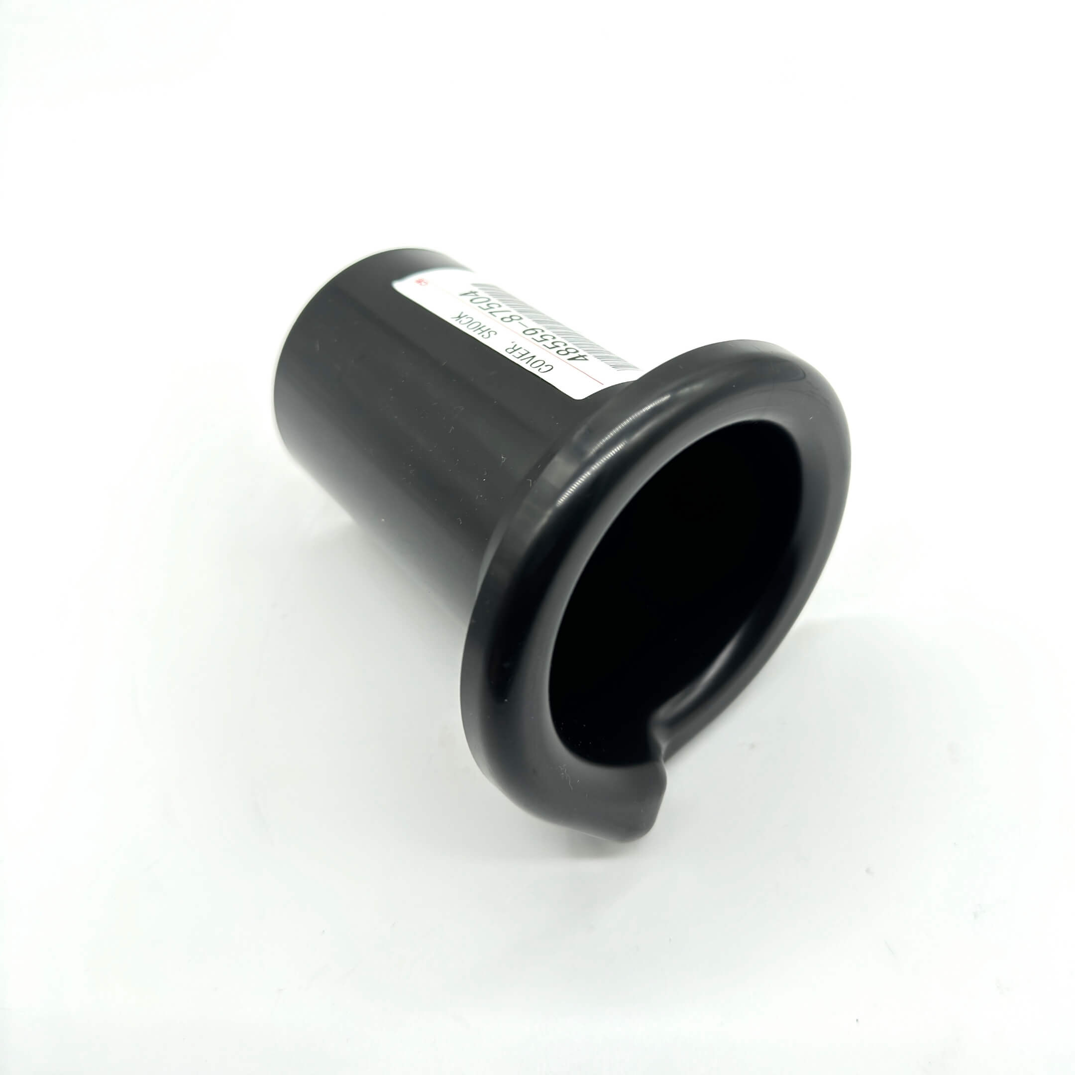
Tie rods, drag links, center arms, knuckles, rack boots and dust seals, plus front wheel bearings and seals. Confirm manual or electric power steering first; drivetrain and ABS also change which parts fit.
Steering components for the Daihatsu Hijet S100 and S110 family, 1994 to 1998. These trucks did not all leave the factory with the same steering. Drivetrain, manual or electric power steering, and ABS all change which parts fit, so identify the truck before ordering.
Confirm manual or electric power steering first; the chassis code does not identify it.
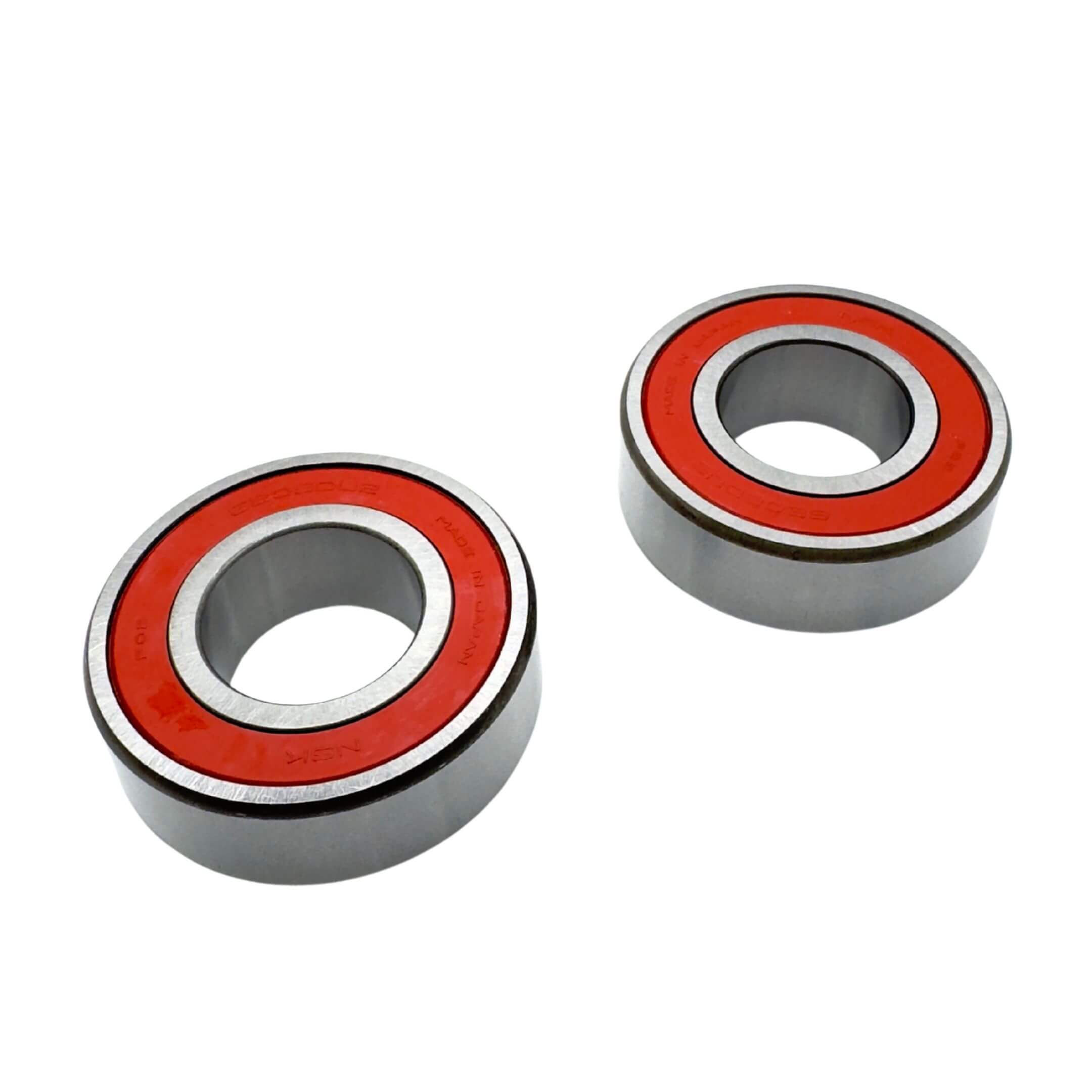
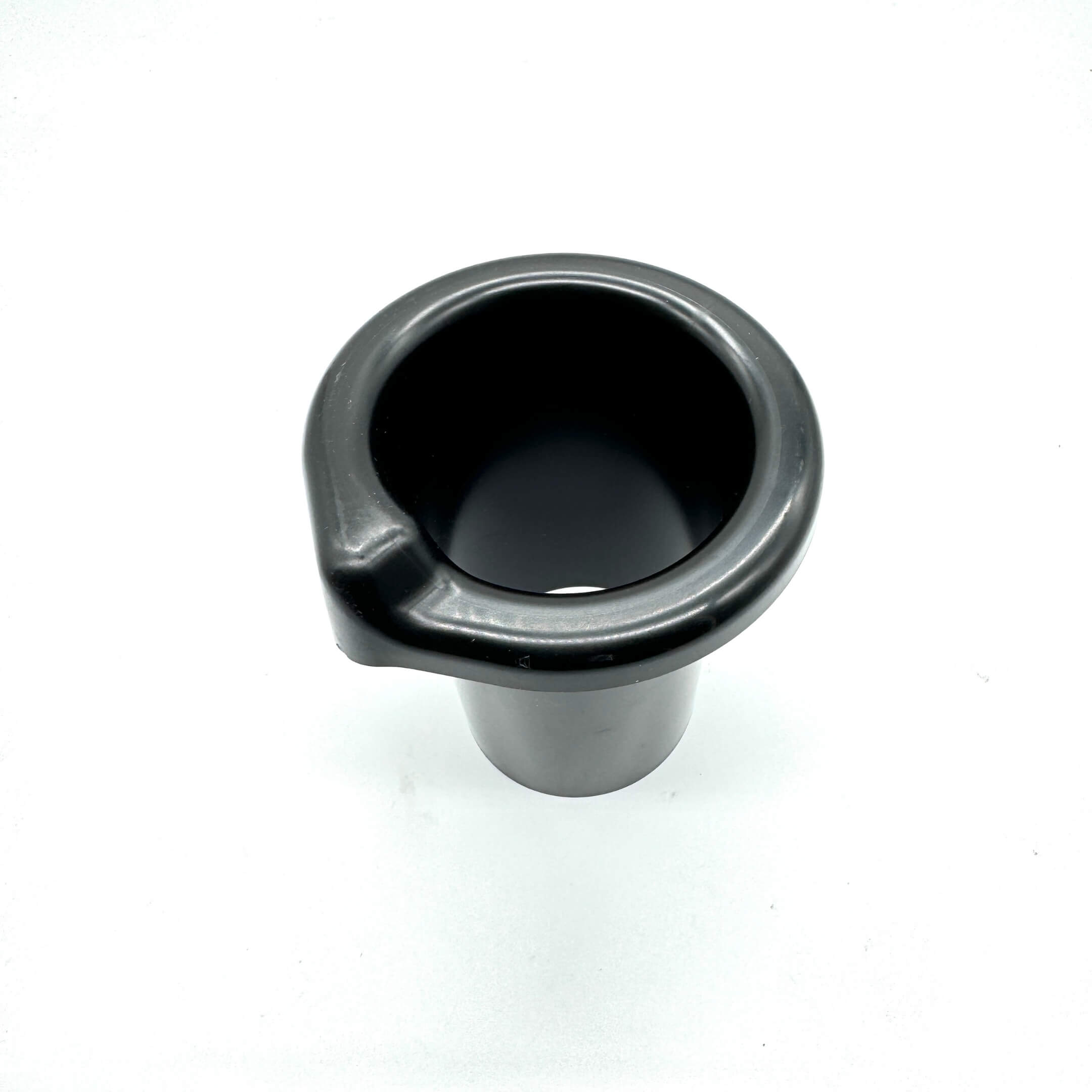
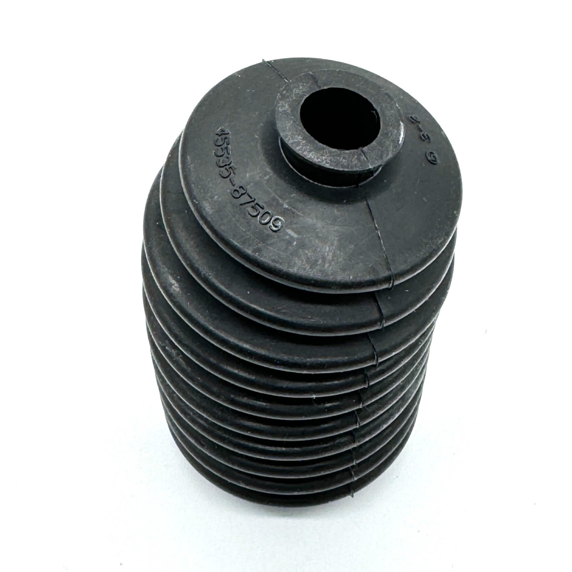
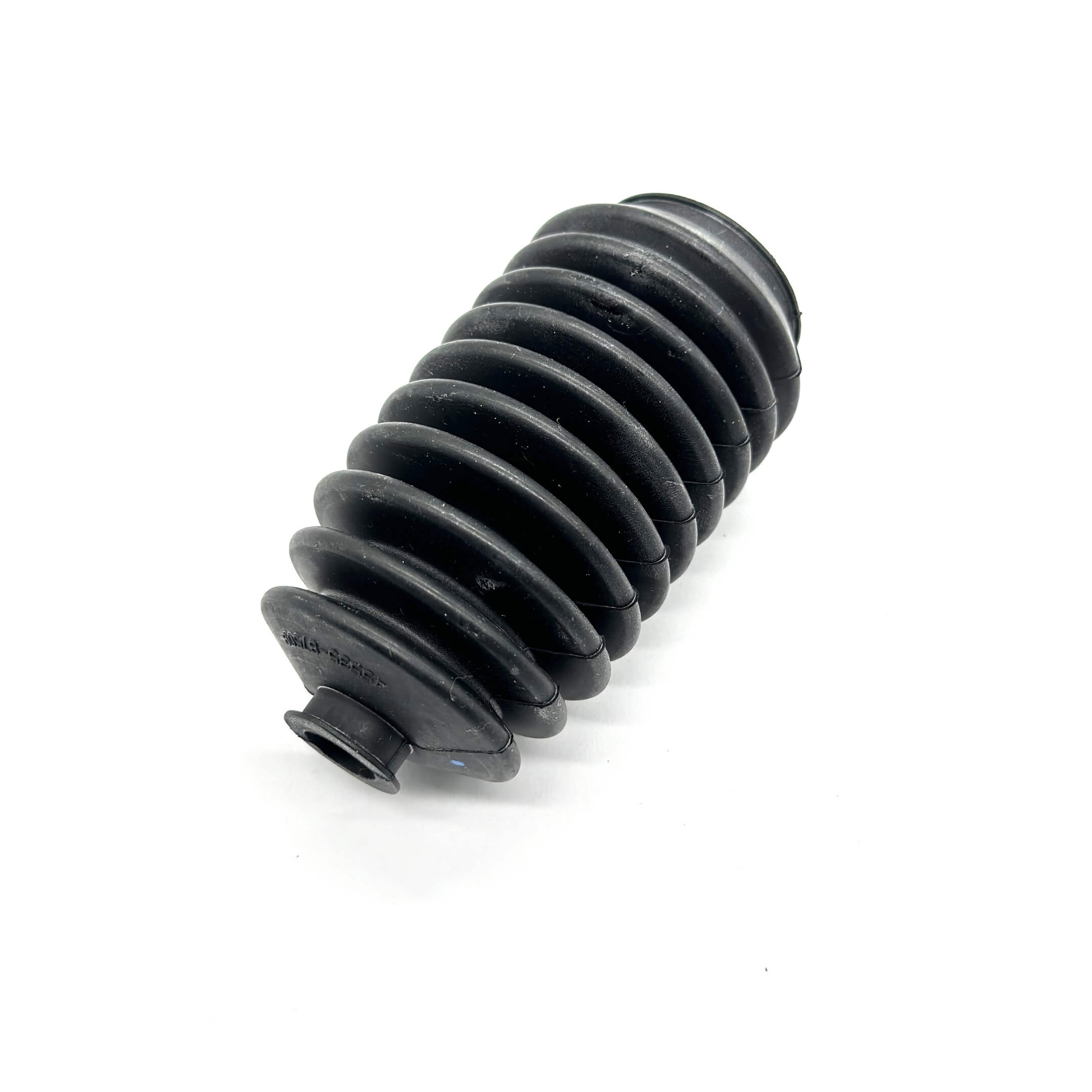
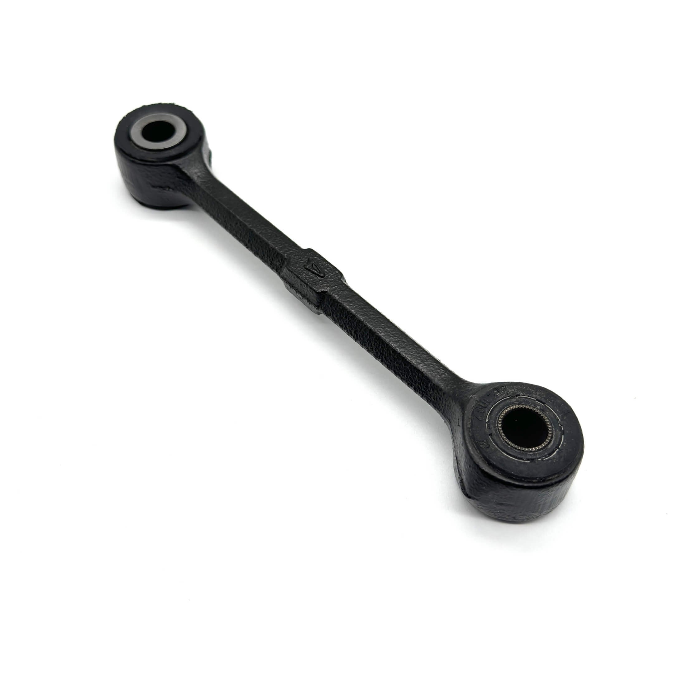
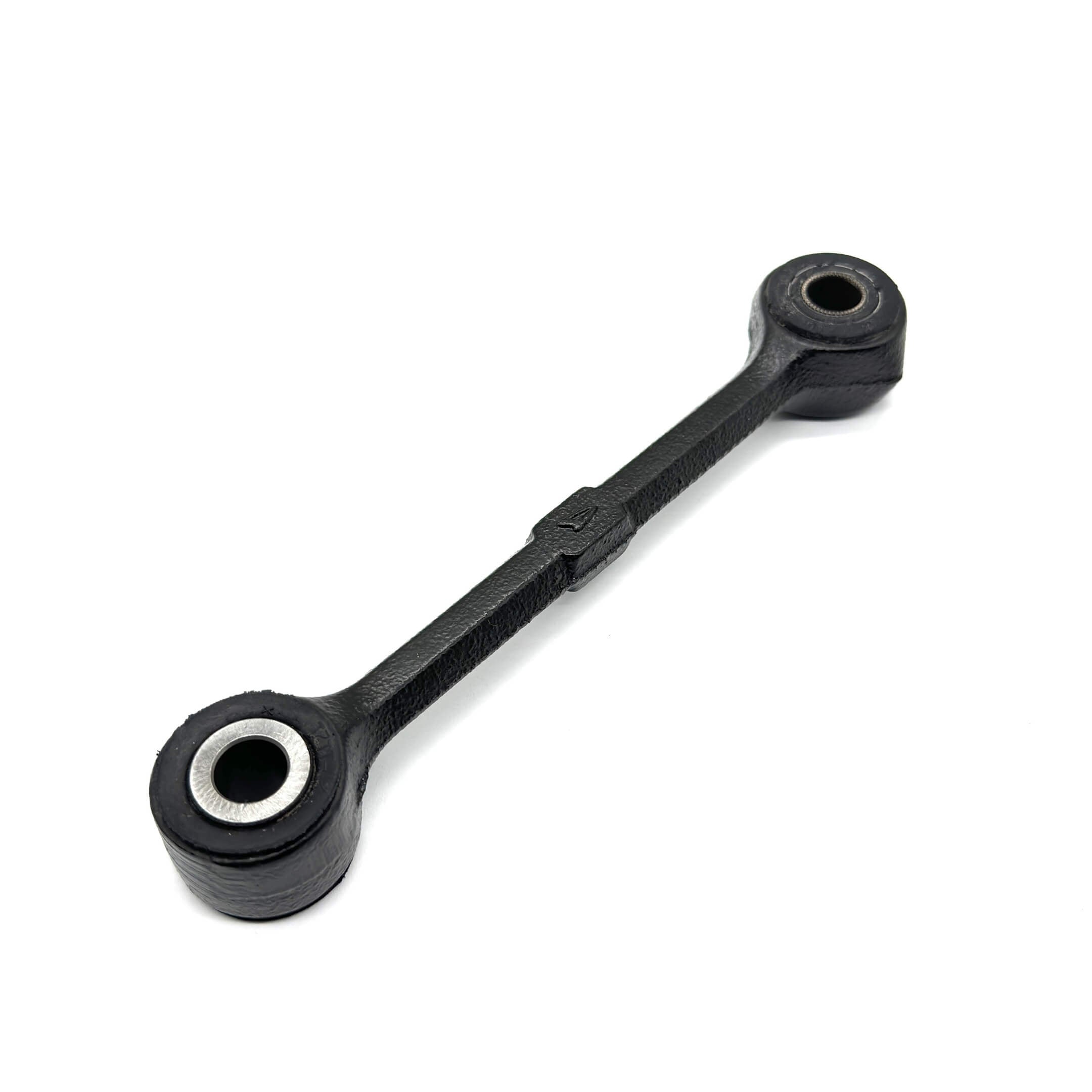
Tie rods, drag links, steering center arms, steering knuckles, rack boots, link dust seals, plus the front wheel bearings and seals that sit alongside them.
The pages below pair Oiwa product guidance with specifications read directly off the original Japanese factory pages. Factory figures are named as factory figures. Practical shop advice is named as ours.
Find Your Truck
Start with the complete CHASSIS NO. On a Hijet it looks like S110P-123456, and it appears on the identification plate, the registration, or the import paperwork. Not every steering part changes with every one of the factors below. Tie rods and rack boots are common across most of the family, while center arms, knuckles, plus the linkage between gear and arm, are the parts that move with configuration.


| What Decides Fitment | Why It Matters |
|---|---|
| Complete CHASSIS NO. | The full code, not just the S100 or S110 prefix. Several steering center arms are split by build date rather than by chassis code, so the prefix on its own does not separate them. |
| Drivetrain, 2WD or 4WD | S100 is 2WD and S110 is 4WD. On 4WD trucks the drive shaft passes through the steering knuckle, which changes the knuckle and the parts that come apart with it. |
| Manual or electric power steering | The chassis code does not tell you this. Manual trucks use a drag link with a tie rod. Electric power steering trucks use relay rod ends with their own torque figures. Look under the truck before ordering linkage. |
| ABS or non-ABS | Steering knuckle kits, plus the inboard front wheel seal behind them, are split by ABS. A sensor and a wire behind the front wheel mean the ABS version. |
| Turbo or T/C application | One factory procedure, the center arm removal, is written specifically for trucks with 4WD, T/C, and electric power steering together. It matters for the job, not for every part on this page. |
Oiwa note. If you cannot tell which steering system is fitted, send us a photo of the linkage between the steering gear and the center arm. That identifies it faster than a chassis code can, because the factory does not map steering type to a chassis code anywhere we can point you at.
Choose Your Parts
These are the steering categories this collection carries. Availability moves, so treat the individual product listing as the source of truth on what is in stock and what fits.
| Category | What You Get | Fitment |
|---|---|---|
| Tie Rods | Inner and outer tie rods, sold individually per side, as a per-side set, or as a complete set covering both sides. | Listed for the truck and van codes across most of this family. Order by side, or take the complete set. |
| Drag Link | The link that runs from the steering gear to the steering center arm, with its pressed-in bushings. | Manual steering trucks. Electric power steering trucks use relay rod ends instead. |
| Steering Center Arm | Center arms, center arm bushings, and steering link joint dust seals. | Our catalog splits these three ways by build date: a standard arm, a power steering arm, then a DOHC arm for the later trucks. That grouping is ours rather than a factory mapping, so send the complete CHASSIS NO. and we will match it. |
| Steering Knuckles & Knuckle Kits | Steering knuckles, and complete kits pairing the knuckle with its wheel bearing and oil seals. | Split by drivetrain and by ABS. Confirm both before ordering. |
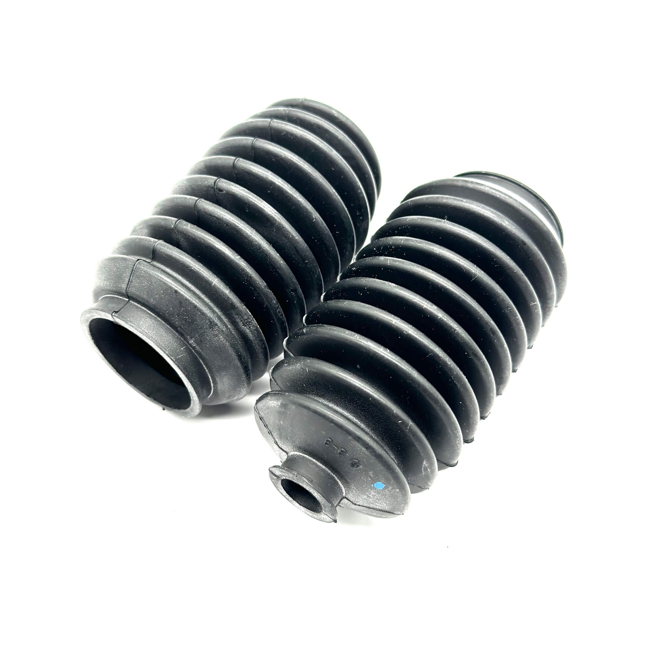
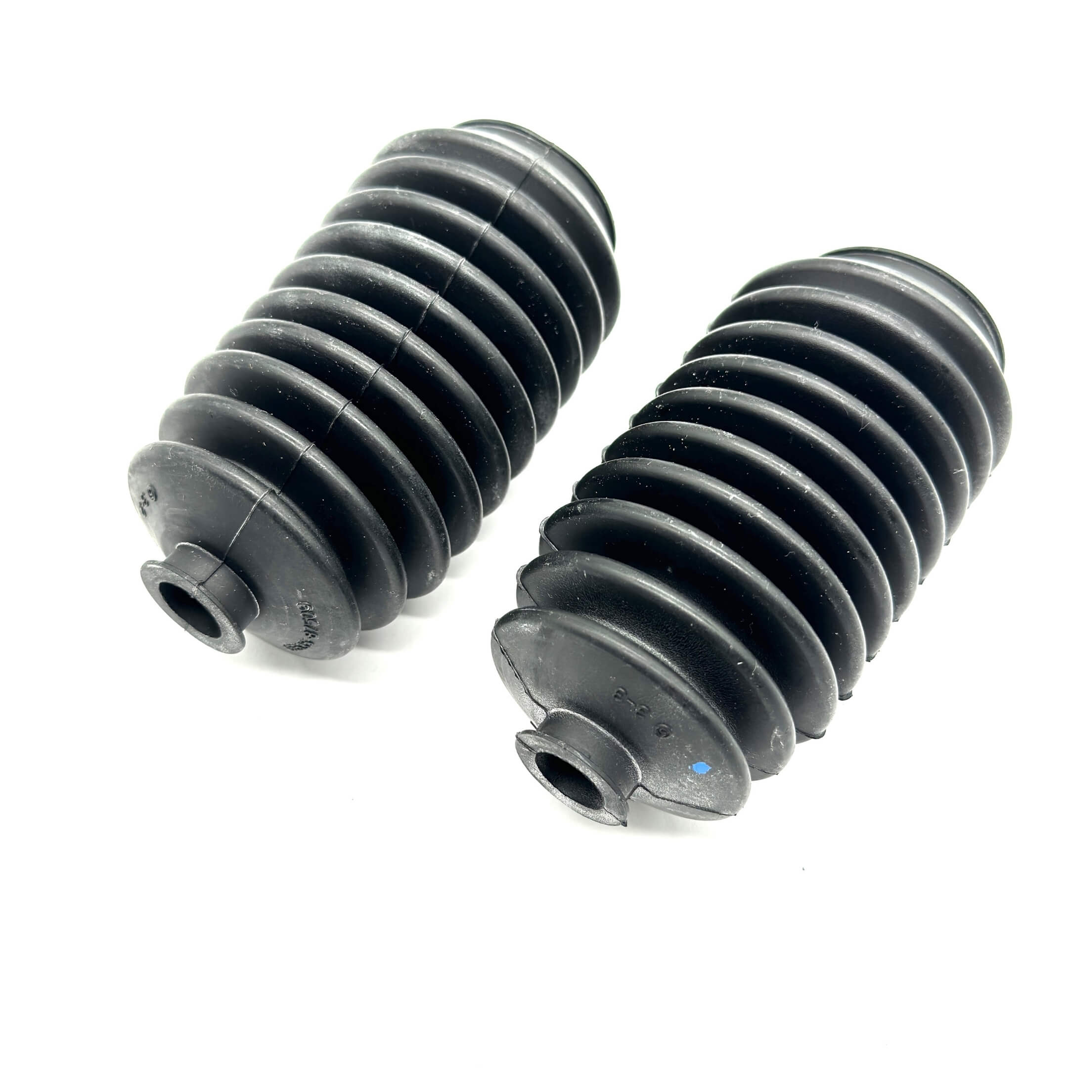
| Rack Boots & Seals | Manual steering rack dust boots, sold singly or as a set, plus steering link joint dust seals. | Manual steering gear. The factory calls for new boots and new bands whenever the rack is opened. |
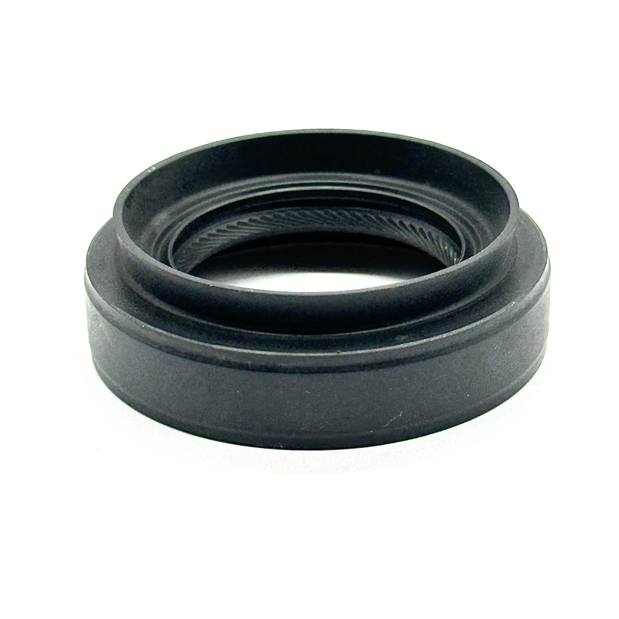
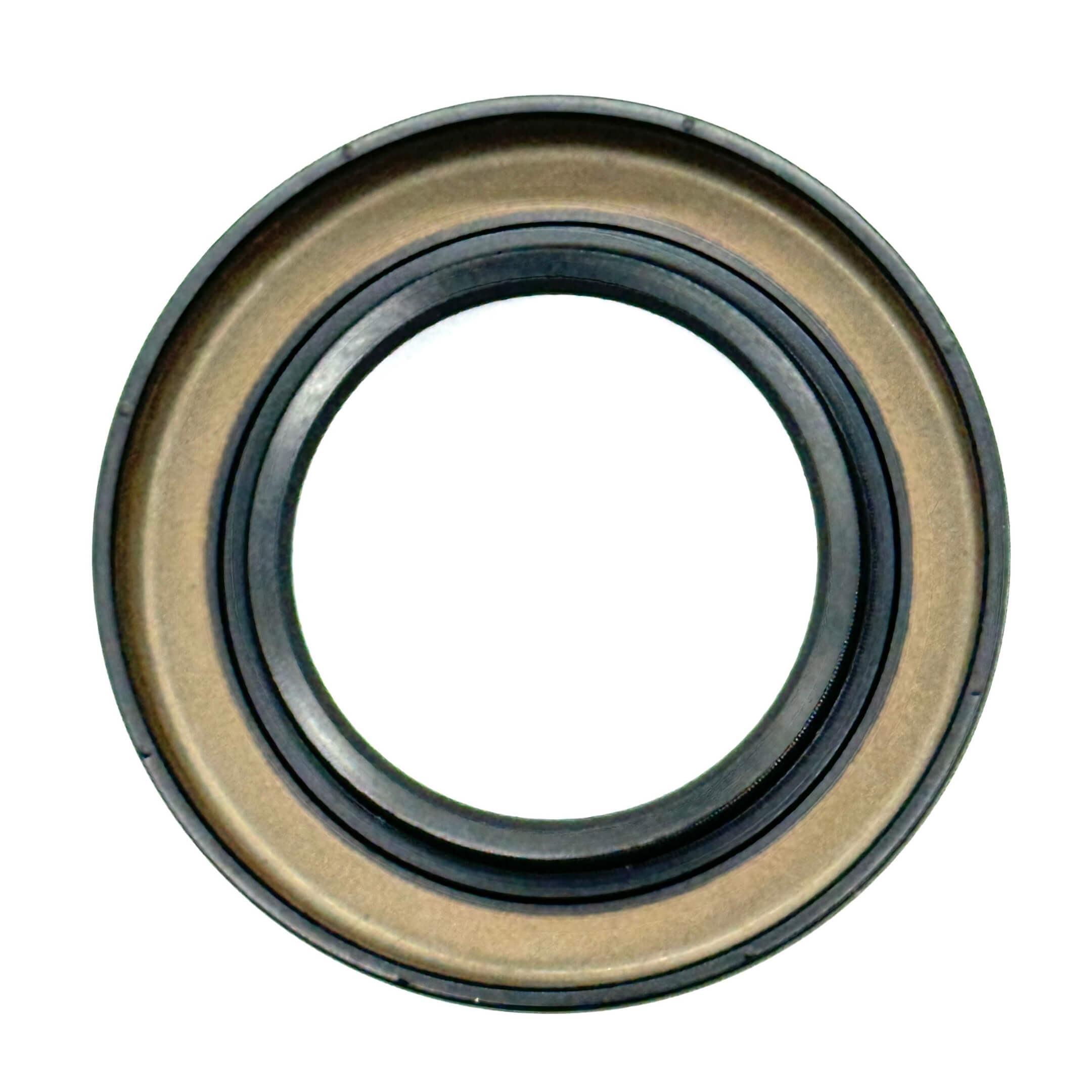
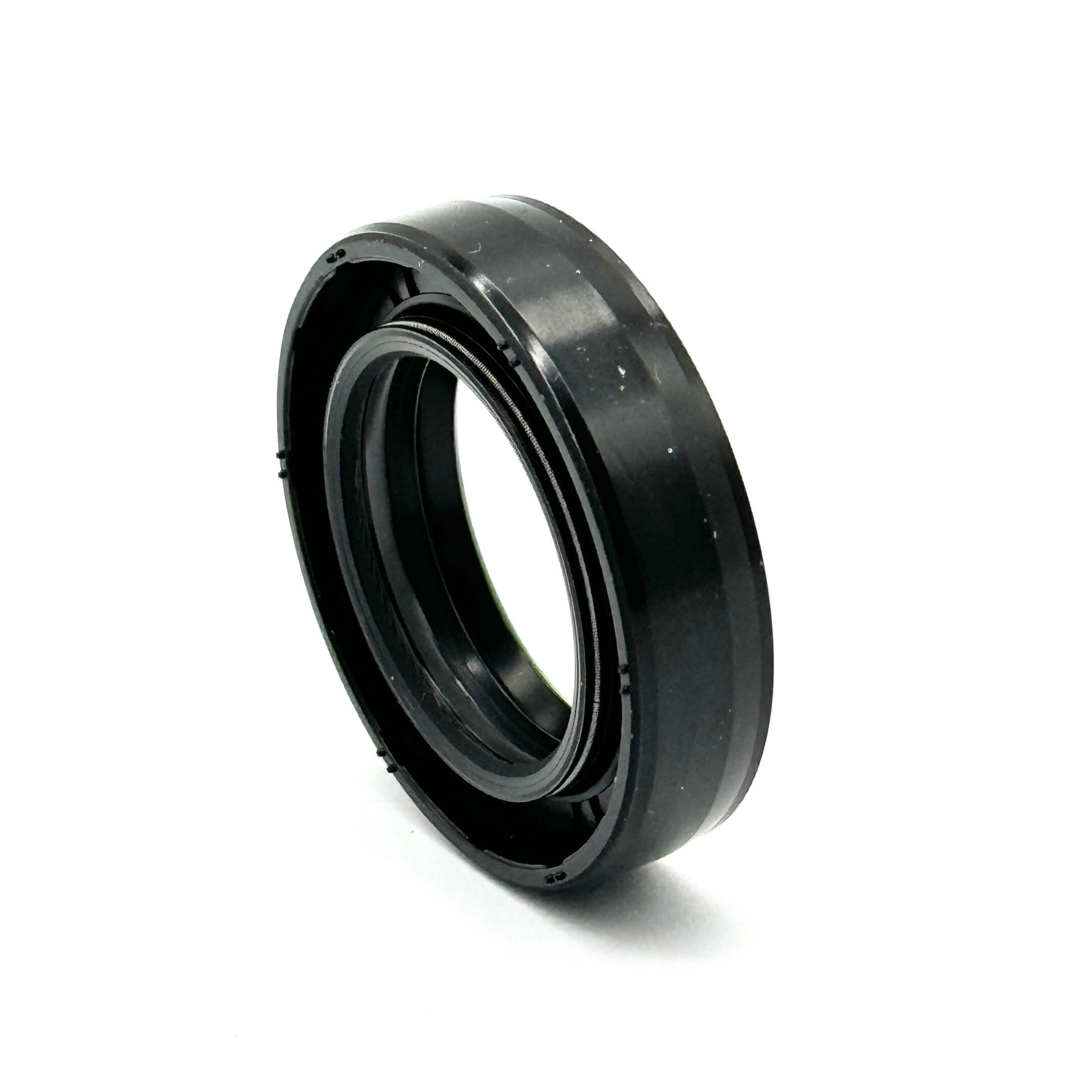
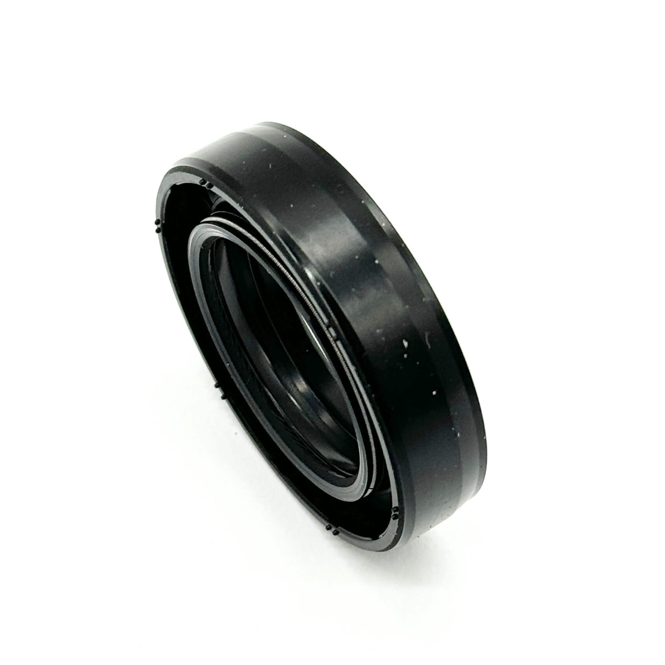
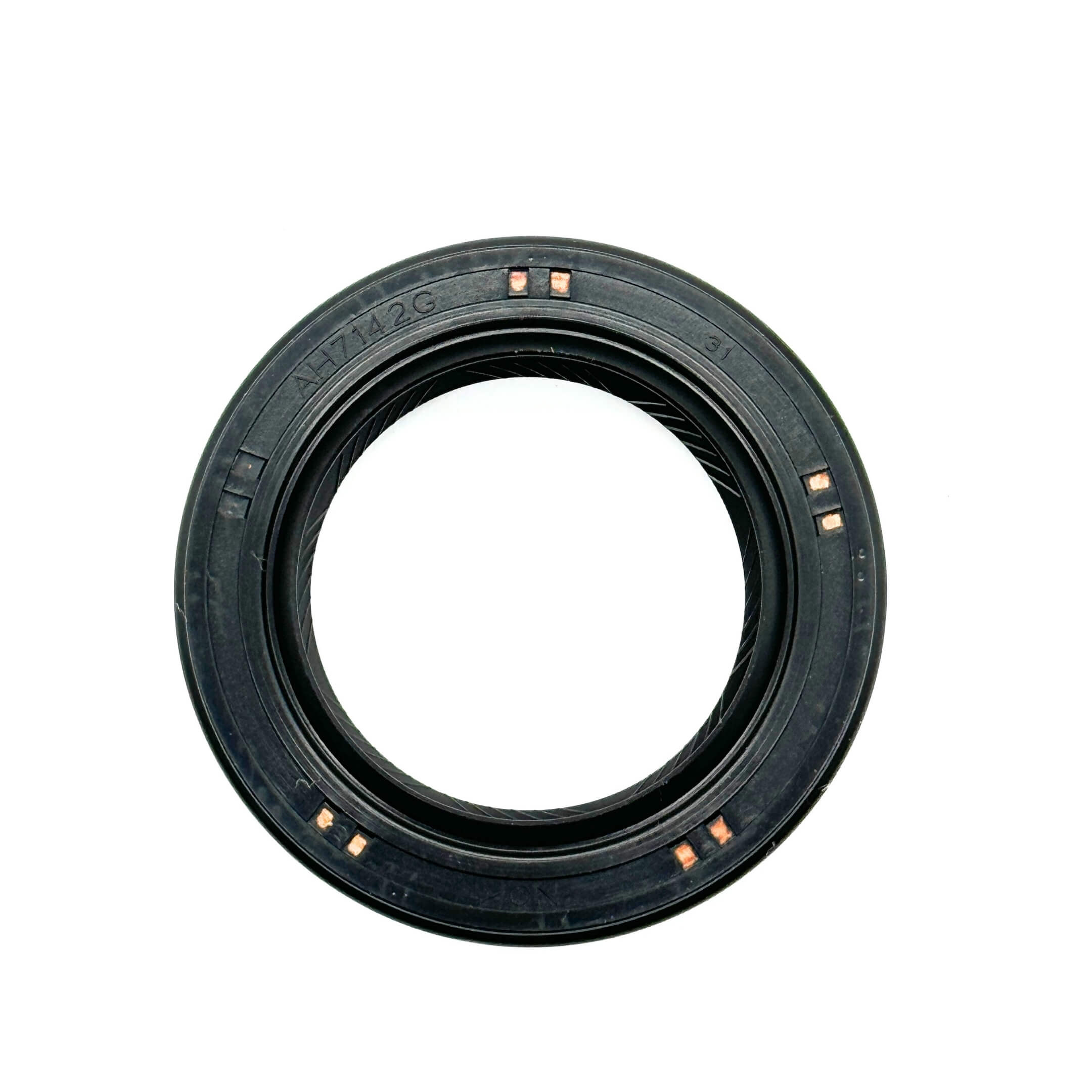
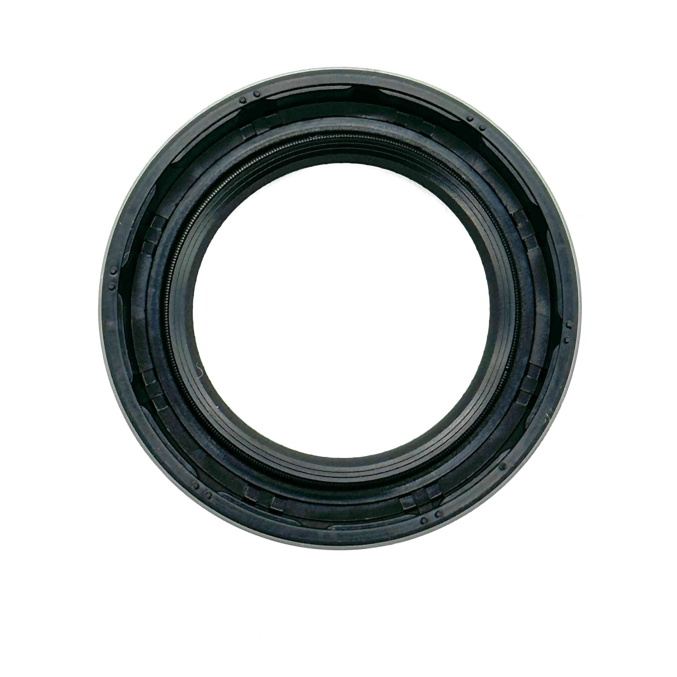
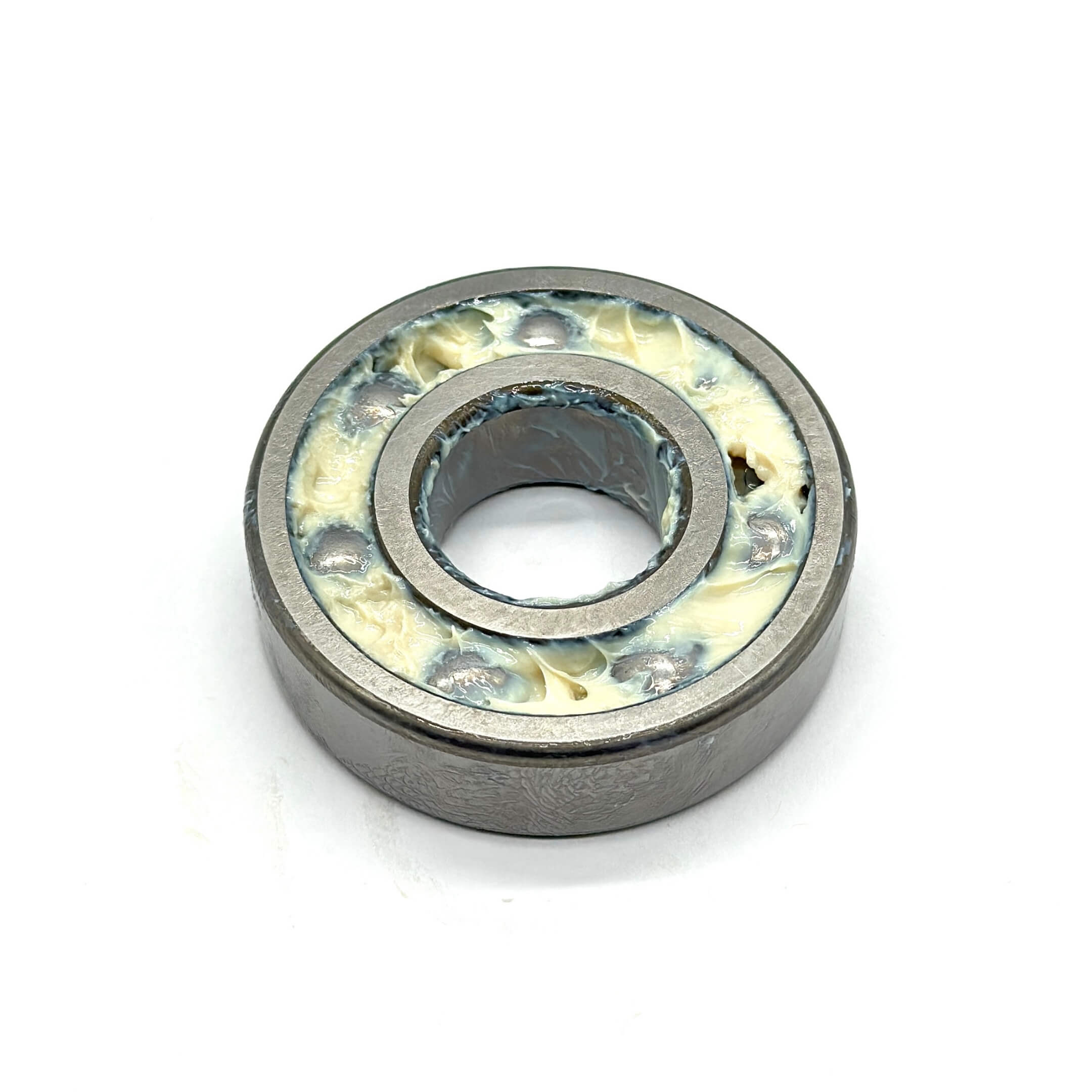
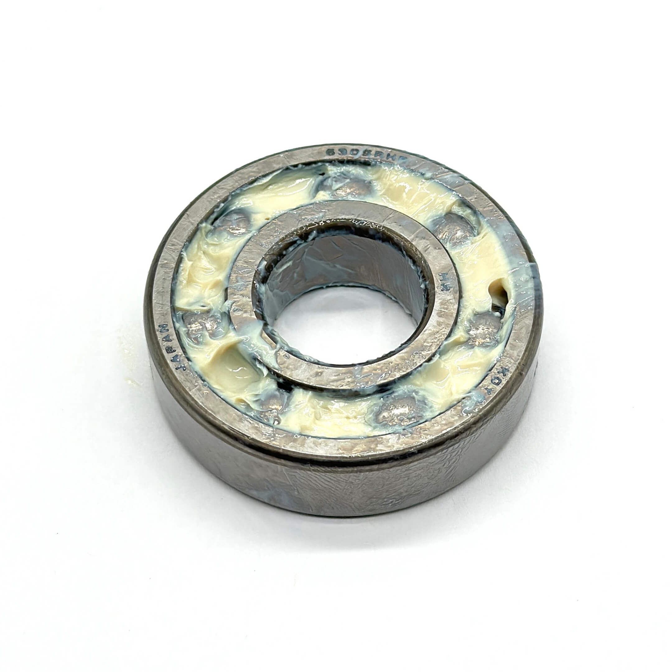
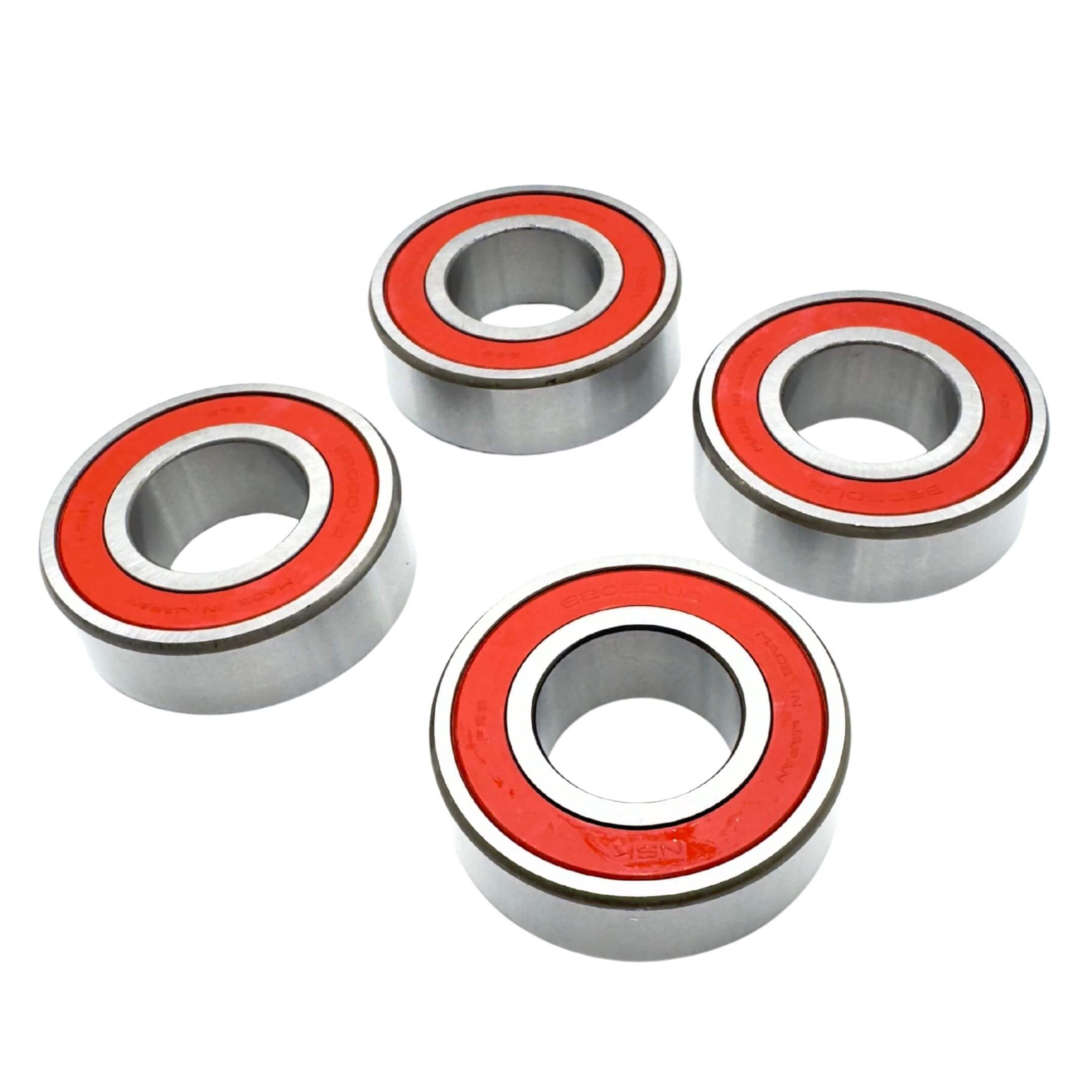
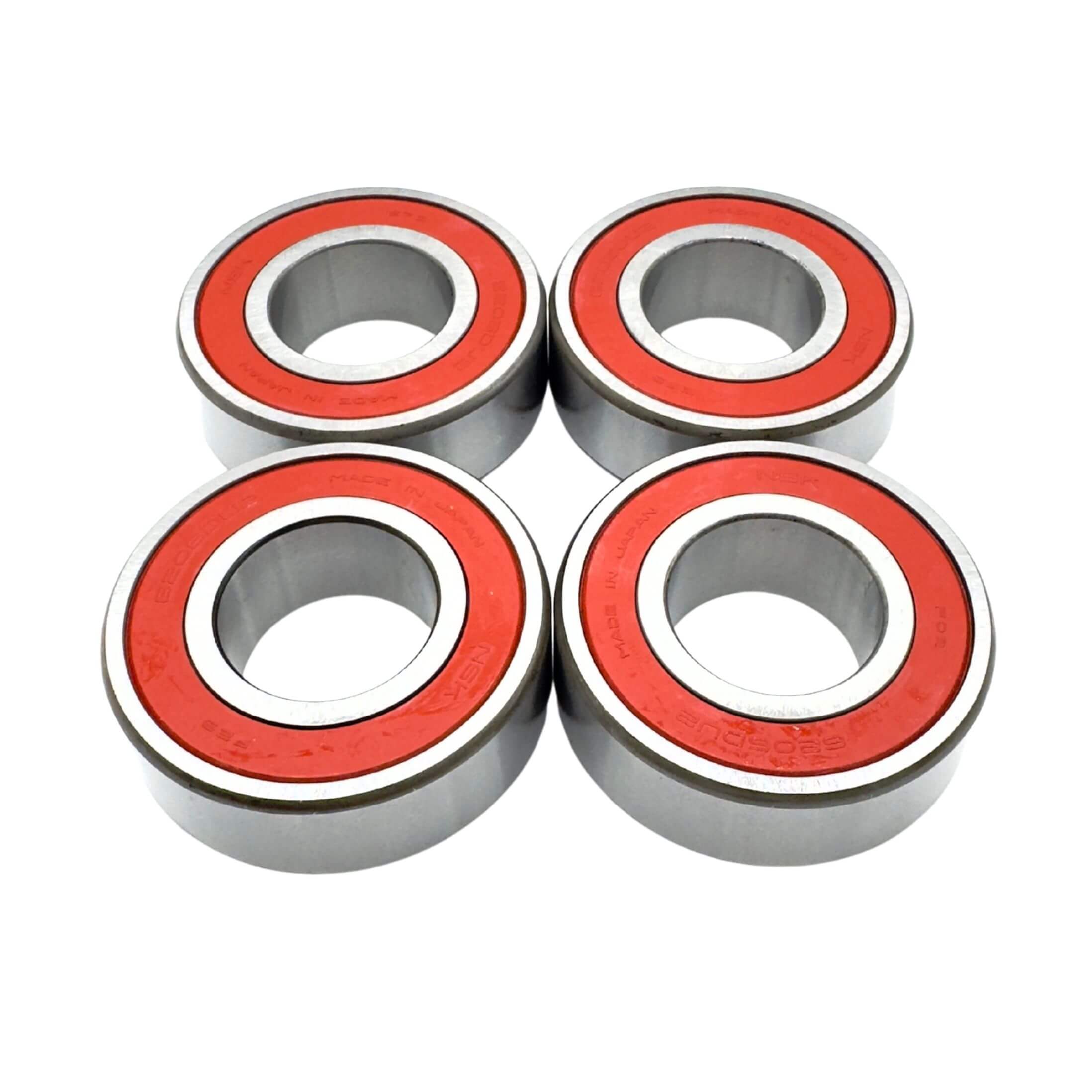
| Front Wheel Bearings & Seals | Front wheel bearings singly, per side, or as complete kits, with inboard and outboard oil seals. | Bearings are shared widely across the family. The inboard seal is split by ABS. |
What a confirmed finding usually means you need
This table starts from something you have already found, not from something you have felt from the seat.
| Confirmed Finding | Typical Part Needed |
|---|---|
| A rack boot is split, cracked, or leaking grease | Rack boot, or the boot set. Fit new bands with it. |
| Play felt directly at a tie-rod ball joint | The affected tie rod end, or the tie rod set for that side. |
| A steering rod is visibly bent or damaged | The affected tie rod, or the drag link. |
| A drag-link bushing is worn, or the link has been removed | Drag link bushings. Once pressed out they cannot go back in. |
| Center-arm bearing or dust seal wear found with the arm off | Needle roller bearing with both dust seals, or the complete center arm. |
| Rack damage verified with the gear apart | Steering gear. The factory prints no rack-bar wear limit to measure against. |
| Front wheel bearing roughness or play confirmed at the hub | Bearing with its oil seals, or the complete bearing kit for that side. |
Symptoms tell you where to inspect. They do not prove which part has failed. Wandering, vibration, looseness, and pulling each have several possible causes, including tire pressure and wheel balance. Work through the factory checks further down this page before buying a part.
Inspection & Service
The factory manual reproduces the Japanese periodic inspection schedule for the steering system, separated into private-use and business-use vehicles. These are Japanese inspection requirements, not United States service requirements.
An inspection interval is not a replacement interval. The factory uses these intervals to trigger inspection. Any adjustment, repair, or part replacement depends on what the inspection finds.
| Inspection Item | Private Use | Business Use |
|---|---|---|
| Steering wheel play, looseness, and rattle | Every 12 and 24 months | Every 3 and 12 months |
| Steering wheel operating condition | Every 12 and 24 months | Every 3 and 12 months |
| Gear box oil leakage | Every 24 months | Every 3 and 12 months |
| Gear box mounting looseness | Every 24 months | Every 3 and 12 months |
| Play at the gear box bearing portion | Not scheduled | Every 12 months |
| Gear backlash | Not scheduled | Every 12 months |
| Rods and arms: looseness, play, and damage | Every 12 and 24 months | Every 3 and 12 months |
| Ball joint dust boot cracking and damage | Every 12 and 24 months | Every 3 and 12 months |
| Wear and mounting condition at connecting portions | Not scheduled | Every 12 months |
| Knuckle arm cracking, and mounting to the knuckle | Not scheduled | Every 12 months |
| Play at the knuckle connecting portion | Every 24 months | Every 3 and 12 months |
| Clearance between knuckle and front axle | Not scheduled | Every 12 months |
| Wheel alignment | Every 24 months | Every 12 months |
| Left and right turning angle | Every 24 months | Every 12 months |
| Power steering belt looseness and damage | Every 6, 12, and 24 months | Every 1, 3, and 12 months |
| Power steering oil leakage and oil quantity | Every 12 and 24 months | Every 1, 3, and 12 months |
| Power steering mounting looseness | Every 24 months | Every 3 and 12 months |
Four of those rows carry an applicability note. Gear backlash is not inspected on the rack and pinion type. The power steering belt row and the power steering oil row are both marked as not required on the electric type. The schedule also prints a belt row and a pump oil row, so it is not written for the electric type alone. The power steering mounting row applies only when the electric type is fitted. Gear box oil leakage carries a separate marker for an initial inspection at one month or 1,000 km.
Every interval mark in the steering block of this schedule is the statutory kind. The one exception is the initial-inspection marker noted above. The schedule also carries a symbol for items the manufacturer merely recommends. It does not appear on a single steering row. We read the schedule off the printed page at high magnification rather than trusting text extracted from the scan.
Manual vs Electric Power Steering
The chassis code identifies 2WD or 4WD. It does not identify the steering system. Manual trucks use a drag link with a tie rod and two tie-rod ends. Electric power steering trucks use relay rod ends with their own torque figures. Inspect the linkage before ordering.
| Where It Sits | Manual Steering | Electric Power Steering |
|---|---|---|
| Gear to center arm | Drag link, bolted straight to both | Drag link end No. 2 into relay rod end No. 2 |
| Center arm side | Drag link onto the arm | Relay rod end No. 2 onto the arm |
| Rack side | Rack end onto the rack | Relay rod end No. 2 onto the rack |
| Between the rods | Tie rod, with an end at each side | Relay rod end No. 1 into No. 2 |
| Rack preload | Set on the rack guide spring cap | 11.5 kgf·cm or less with the rack boots installed |
The center arm removal procedure is written for one configuration. The factory heads that procedure for trucks with 4WD, T/C, and electric power steering fitted together. It involves the front suspension crossmember together with the front differential mount, neither of which a 2WD truck presents the same way. We are not extending that scope to other trucks, because the factory does not.
Alignment & Turning Angle
Oiwa recommendation. Because tie-rod length directly affects toe, verify front toe after replacing or disturbing steering linkage components.
The factory measures with the vehicle settled: rock it, then push it straight forward about 5 m. If the truck has been reversed, move it forward again by the same distance before measuring.
| What Is Measured | Pickup | Van and Atrai |
|---|---|---|
| Toe-in | 0 ± 1.0 mm | 0 ± 1.0 mm |
| Camber | 0°15′ ± 45′ | 0°15′ ± 45′ |
| Caster | 3°08′ ± 1° | 3°04′ ± 1° |
| Kingpin inclination | 13°03′ ± 1° | 13°03′ ± 1° |
| Side slip | IN 5 to OUT 5 mm | IN 5 to OUT 5 mm |
For front wheel geometry, toe and wheel turning angle are adjustable. Camber, caster, and kingpin inclination are factory-set and non-adjustable. The factory states this directly. Caster is the one figure that differs between pickup and van, which is why body type matters. If a non-adjustable value reads out of range after an impact, look for bent or damaged parts rather than for an adjustment.
Toe is set by turning the left and right rack ends by equal amounts in opposite directions. Keep the two rack-end lengths equal. The factory gives the reason plainly: unequal lengths produce a difference in wheel turning angle. Do not twist the boots while adjusting. Tighten the tie-rod-end locknuts to 450 ± 100 kgf·cm.


The factory prints more than one turning angle figure. The inspection schedule and the adjustment section give 36°20′ inner with 34°45′ outer. The service standard table gives 36° inner with 34° outer. The wheel turning angle procedure gives 36° inner with 35° outer. All three carry the same tolerance of zero over, up to 3° under. The adjustment you make is the same in every case, at the two rack ends. See Factory Notes for the full comparison.
Troubleshooting & Factory Checks
Work outward from the steering wheel. Each check narrows the field. None of them on its own names a failed part, which is why the last column describes what you are looking at rather than what to buy. You will need a helper and a safe way to raise the front of the truck.
| Factory Check | How To Check It | What To Look For |
|---|---|---|
| Steering wheel free play | Wheels straight ahead. Turn the rim gently until the tires just begin to move, and measure the travel at the rim. | The factory range is 0 to 30 mm, the same for manual and power steering. Travel beyond it calls for further inspection of the steering system. |
| Steering wheel looseness | Move the wheel up, down, side to side, then toward and away from the dash. | Abnormal looseness or play. This is an inspection finding, not a diagnosis of any one component. |
| Steering operation on the road | Drive it and pay attention to how it behaves. | Shake, pull, heavy effort, or a wheel that will not return to center. |
| Gear box leakage | Wipe the housing and boots clean, then look them over. | Grease escaping, a split boot, or a cracked housing. |
| Gear box mounting looseness | Helper turns the wheel roughly 90 degrees each way while you watch the mounts. | The gear itself shifting against the floor. |
| Rack bar and support play | Move the rack end by hand and feel the bar behind it. | Play in the bar itself, separate from play at the joint. |
| Steering rods and arms | Front raised. Move every joint by hand, then sight down each rod. | Play at a joint, a bent rod, or visible damage. |
| Ball joint dust boots | Look over each dust boot on the steering arms. | Cracking or damage. The factory treats the boot condition as a separate inspection item; this check does not make the boot a routine single-use part. |
| Linkage connections | Check each tie rod end sits properly in the knuckle, and that its clip is present. | Wear at the connection, or a missing clip. |
| Knuckle arm condition | Look for cracks, and check each arm is tight where it meets the knuckle. | Cracking, or a loose mounting. |
| Knuckle connection play | Raise the truck until the spring hangs free, hold the brakes, and rock the tire. | Play felt at the 12 and 6 positions. |


Free play inside the range does not certify the rest of the steering. The factory inspects the gear box mounting, the rack bar, the rods and arms, the joints, the dust boots, the knuckle arms, and the knuckle connections as separate items, each with its own interval. A pass on the wheel is one result out of eleven.
Check the cheap things first. Tire pressure on these trucks is not one number. It changes with body code, tire size, and in one case with the transmission. Read the tire pressure caution plate on your own truck and confirm the pressure for the exact tire size fitted before you chase a pull or a wander through the linkage. Minimum tread depth is 1.6 mm.
Installation & Single-Use Parts
Two factory cautions before the puller goes near a tie-rod end. Thread a spare nut onto the stud first, so the tool presses on the nut rather than on the threads. Then tie the puller to the body with a strap, which is there to stop the tool dropping when the joint releases. The separation tool is SST 09611-87701-000.
Mark the ends before you take them off. The factory uses matching marks on the No. 1 and No. 2 ends so the assembly goes back to the same length. The clips that retain the ends are single use, at the center arm and at both steering knuckles alike.
When you fit new tie rod parts rather than reusing the old ones, build the assembly to the factory dimension of 570 to 574 mm. That figure is measured ball stud center to ball stud center, not end to end, and the same drawing shows 15 ± 3 mm of thread at each side. The 570 to 574 mm assembly dimension is a starting specification for new parts, not a substitute for checking toe after installation.
The drag link is directional. The factory shows which end faces the steering gear and which faces the center arm, and says only that the direction must not be reversed. Its bushings are single use once pressed out. Press each new bushing until it stands 3 ± 1 mm proud at each end, and no farther. Two tools are listed for that job: SST 09301-87701-000 with SST 09506-30011-000.


| What You Are Tightening | kgf·cm | ft-lb |
|---|---|---|
| Tie rod assembly to tie rod end No. 1 and No. 2 | 450 ± 100 | 33 ± 7 |
| Tie rod end to steering knuckle | 475 ± 75 | 34 ± 5 |
| Tie rod end to steering center arm | 475 ± 75 | 34 ± 5 |
| Steering drag link to steering gear | 800 ± 100 | 58 ± 7 |
| Steering drag link to steering center arm | 800 ± 100 | 58 ± 7 |
| Steering gear to floor | 625 ± 75 | 45 ± 5 |
| Intermediate shaft, either end | 250 ± 50 | 18 ± 4 |
Oiwa recommendation. After disturbing any linkage joint, check the dust boot on that joint before the truck goes back on the ground. The factory inspects those boots on their own schedule, and a boot that was already cracked is easiest to catch while the front end is still apart.
Rack, Center-Arm & Single-Use Parts
This is bench work. The rack guide sets how hard the rack presses on the pinion, and the starting force tells you whether the setting is right.
| What You Are Setting | The Figure | Why It Matters |
|---|---|---|
| Rack guide spring cap | Tighten to 70 kgf·cm, then back off 50° [+5, -5]° | The back-off sets the load. The tightening figure alone is not the setting. |
| Starting force, manual gear, boots off | 14 kgf·cm or less | Measured on the bench with a preload gauge. |
| Starting force, manual gear, boots on | 17 kgf·cm or less | Oiwa note: boots add drag, which is why this is the higher of the two limits. The electric power steering gear is held to a different figure. |
| Rack end fitting angle | 12°11′ ± 1° | Check it again after tightening. The nut moves it. |
| Rack boot band No. 1 position | Clocked to approximately 45° | A clocking position, not a torque. The factory prints no tolerance on it. |
| Center arm needle bearing | Pressed to 6.0 to 6.3 mm | A depth, not a torque. The factory prints the depth without saying what happens outside it. |
| Center arm dust seal No. 2 | Pressed to 0.1 to 0.7 mm | Almost flush. Oiwa note: easy to push past on the first attempt. |
If the starting force comes in over the limit, the factory sends you back to the rack guide spring cap to redo the adjustment. It does not treat a high reading as a reason to replace the rack.


Center arm work needs six special tools, listed together in the factory preparation table: SST 09611-87502-000, SST 09611-87503-000, SST 09611-87504-000, SST 09611-87505-000, SST 09611-87506-000, and SST 09506-87304-000. They are not all used at once. One is for removal only, three are install drivers used one per component, and two appear in every press operation as the ram with its base support. The drag-link bushings need two further tools of their own.
Oiwa recommendation. This job wants a press, six factory tools, and a preload gauge. For most owners, fitting a complete center arm or a complete steering gear is the more practical route than rebuilding one.
Parts the factory specifies new, by service operation
These are the parts the factory explicitly marks as non-reusable, or instructs you to fit new. A part is on this list only where the factory says so for that operation.
| Service Operation | Factory-Specified New / Non-Reusable Parts |
|---|---|
| Manual steering gear, disassembly and assembly | Rack boots left and right, rack boot No. 1 bands, rack boot No. 2 bands, pinion dust cover, rack guide O-ring, Type K oil seal, snap ring, shaft snap ring, radial ball bearing, and the retaining ring. |
| Electric power steering gear, disassembly and assembly | Rack boots left and right, rack boot No. 2 bands, and rack boot No. 3 bands. |
| Drag link, removal and installation | Both bushings. Once pressed out they cannot go back in. |
| Tie rod, removal and installation | The retaining clips, at the center arm and at both steering knuckles. |
| Steering center arm, removal and installation | The retaining clip. |
| Steering center arm, disassembly and assembly | Steering link dust seal No. 1, steering link dust seal No. 2, and the needle roller bearing. |
A ball-joint dust boot is not on that list. The factory tells you to inspect these boots for cracking and damage. That is an inspection item, not a part the factory requires you to renew every time the joint is disturbed. Steering gear removal and installation, as opposed to disassembly, designates no non-reusable parts at all.
Specifications
The master numerical reference for this page. Figures in kgf·cm are the factory values.
Steering and alignment standards
| Item | Figure | Applies To |
|---|---|---|
| Steering wheel free play | 0 to 30 mm | Manual and power steering alike |
| Toe-in | 0 ± 1.0 mm | All |
| Camber | 0°15′ ± 45′ | All, non-adjustable |
| Caster | 3°08′ ± 1° | Pickup, non-adjustable |
| Caster | 3°04′ ± 1° | Van and Atrai, non-adjustable |
| Kingpin inclination | 13°03′ ± 1° | All, non-adjustable |
| Front side slip | IN 5 to OUT 5 mm | All |
| Minimum tire tread depth | 1.6 mm | All |
Manual steering gear standards
| Item | Figure | Notes |
|---|---|---|
| Rack guide spring cap setting | Tighten 70 kgf·cm, back off 50° [+5, -5]° | The back-off is the setting. |
| Rack starting force, boots removed | 14 kgf·cm or less | Manual gear, bench measurement. |
| Rack starting force, boots fitted | 17 kgf·cm or less | Manual gear, bench measurement. |
| Rack end installation angle | 12°11′ ± 1° | Recheck after tightening. |
| Rack boot band No. 1 position | Approximately 45° | No tolerance is printed. |
Electric power steering gear standard
| Item | Figure | Condition |
|---|---|---|
| Power steering gear preload | 11.5 kgf·cm or less | Rack boots installed |
Tie rod, drag link, and center arm standards
| Item | Figure | Notes |
|---|---|---|
| New tie rod assembly dimension | 570 to 574 mm | Ball stud center to ball stud center. |
| Tie rod thread showing each side | 15 ± 3 mm | Keep both sides equal. |
| Drag link bushing projection | 3 ± 1 mm | At each end. Do not press farther. |
| Center arm needle bearing press depth | 6.0 to 6.3 mm | Install only. |
| Center arm dust seal No. 2 press depth | 0.1 to 0.7 mm | Install only. |
| Center arm dust seal No. 1 press depth | Not published | The factory prints no depth for this seal. |
Grease quantities
| Where It Goes | Quantity | Grease |
|---|---|---|
| Rack guide cavity in the housing | 6 to 8 g | Amix EP |
| Sintered bushing area in the housing | 0.3 ± 0.1 g | Amix EP |
| Needle bearing area in the housing | 1.0 ± 0.2 g | Amix EP |
| Rack shaft area | 1 g | Amix EP |
| Rack tooth surface | 4 g | Amix EP |
| Boot small-diameter seating area | Thin coat | Amix EP |
| Type K oil seal lip | 0.3 ± 0.1 g | Amix long-life chassis |
| Pinion dust cover | 1 g | Amix EP |
| Center arm bearing bore and both seal faces | Not quantified | Amix MP |
Steering wheel and column torques
| What You Are Tightening | kgf·cm | ft-lb |
|---|---|---|
| Steering wheel to steering column shaft | 350 ± 50 | 25 ± 4 |
| Steering wheel to horn button contact plate | 75 ± 25 | 5.4 ± 1.8 |
| Horn button contact plate to horn button harness | 125 ± 25 | 9.0 ± 1.8 |
| Steering column shaft to universal joint | 250 ± 50 | 18 ± 4 |
| Steering column to ignition switch | 130 ± 30 | 9.4 ± 2.2 |
| Steering column to pedal support | 130 ± 30 | 9.4 ± 2.2 |
Manual steering gear and drag link torques
| What You Are Tightening | kgf·cm | ft-lb |
|---|---|---|
| Steering gear to drag link | 800 ± 100 | 58 ± 7 |
| Drag link to steering center arm | 800 ± 100 | 58 ± 7 |
| Steering gear to floor | 625 ± 75 | 45 ± 5 |
| Intermediate shaft to steering gear | 250 ± 50 | 18 ± 4 |
| Intermediate shaft to steering column shaft | 250 ± 50 | 18 ± 4 |
| Hexagon nut to steering gear housing | 400 ± 50 | 29 ± 4 |
| Steering rack to steering rack end No. 1 | 600 ± 100 | 43 ± 7 |
| Strut bar bracket to frame | 1,150 ± 150 | 83 ± 11 |
| Strut bar to lower arm | 950 ± 150 | 69 ± 11 |
Tie rod and center arm torques
The factory files the crossmember rows with the front differential row into its own center arm table. Those belong to the center arm job on a 4WD truck. A 2WD truck has no front differential to disconnect.
| What You Are Tightening | kgf·cm | ft-lb |
|---|---|---|
| Tie rod assembly to tie rod end No. 1 and No. 2 | 450 ± 100 | 33 ± 7 |
| Steering center arm to tie rod end | 475 ± 75 | 34 ± 5 |
| Steering knuckle to tie rod end | 475 ± 75 | 34 ± 5 |
| Steering center arm to suspension crossmember | 1,300 ± 100 | 94 ± 7 |
| Suspension crossmember to frame | 1,150 ± 150 | 83 ± 11 |
| Front differential mount to front differential, 4WD | 425 ± 75 | 31 ± 5 |
| Relay rod end No. 2 to steering center arm | 625 ± 75 | 45 ± 5 |
Electric power steering linkage torques
| What You Are Tightening | kgf·cm | ft-lb |
|---|---|---|
| Drag link end No. 2 to relay rod end No. 2 | 1,100 ± 220 | 80 ± 16 |
| Relay rod end No. 2 to steering center arm | 625 ± 75 | 45 ± 5 |
| Relay rod end No. 2 to steering rack | 575 ± 75 | 42 ± 5 |
| Relay rod end No. 1 to relay rod end No. 2 | 450 ± 50 | 33 ± 4 |
| Steering gear to floor | 625 ± 75 | 45 ± 5 |
| Intermediate shaft to steering gear | 250 ± 50 | 18 ± 4 |
The kgf·cm column is the factory figure. The ft-lb column is ours. Converted at 1 kgf·cm to 0.0723 ft-lb and rounded to a number you can set a wrench to. Where the two disagree, the factory column wins. Four rows on this page fall under 10 ft-lb, all of them in the steering wheel and column table. Those set more accurately on an inch-pound wrench than on a foot-pound one.
Factory Notes
Where the factory prints two answers, we keep both rather than pick one.
Wheel turning angle
Three different figures are printed across the factory sources, all carrying the same tolerance of zero over, up to 3° under.
| Factory Source | Inner | Outer |
|---|---|---|
| Periodic inspection schedule | 36°20′ | 34°45′ |
| Turning angle adjustment values | 36°20′ | 34°45′ |
| Service standard table | 36° | 34° |
| Wheel turning angle procedure | 36° | 35° |
Two of those pages carry the same factory illustration reference while printing different outer values, which points at a plate reuse rather than at three separate engineering positions. The factory gives no basis for choosing between them, so we are not choosing. The adjustment itself is unaffected: it is made at the two rack ends in every version.
Tire pressure is not one number
There is no single S100 and S110 tire pressure. The pickup and cab-chassis codes run 2.0 front with 2.4 rear. The van codes run higher, and one of them changes with the transmission fitted. Printed combinations across the family include 2.0 with 2.4, 2.2 with 2.4, 2.4 with 2.4, 2.4 with 2.6, 2.2 with 2.2, and 2.6 with 2.6, all in kgf/cm², plus 4.2 for the temporary spare. Read the caution plate on your own truck and match the exact tire size fitted.
The S110V pressure disagreement
For the S110V on 5.00-12 tires, the factory contradicts itself. Four separate pages give 2.4 front with 2.4 rear. The service standard table gives 2.4 front with 2.6 rear, and merges two tire sizes into the row where the other pages keep them apart. Both are factory-printed. We have not resolved it.
Center arm procedure scope
The detailed center arm removal procedure is headed for trucks with 4WD, T/C, and electric power steering fitted together. The disassembly procedure that follows it carries no application qualifier at all. We are not reading the narrow heading as a general S100 and S110 statement, and we are not reading the missing one as proof that the bench work applies to every truck either.
Boot band clocking
The rack boot No. 1 band position is printed as approximately 45°. No tolerance appears anywhere on that drawing. Any tighter figure you see quoted for this, ours included in earlier versions of this page, was not read off the factory drawing.
One tool number, printed two ways
The variable open wrench used on the rack is listed as 09222-10010-000 in one preparation table and as 09922-10010-000 in the body text of the same chapter, then again as 09922-10010-000 in the power steering chapter. The second form appears more often. We are reporting both rather than silently correcting one.
Where the alignment procedure actually lives
The wheel alignment and turning angle procedures are not in the steering chapter. They sit in the suspension chapter, which is worth knowing if you are working from the original book and cannot find them next to the steering gear.
Where can I buy Daihatsu Hijet steering parts in the United States?
Oiwa Garage supplies Daihatsu Hijet steering parts from our California warehouse. Availability varies by part, so check the individual product listing. Not sure you selected the right parts? Add your complete CHASSIS NO. at checkout and we will verify fitment before shipping.
Our 100% Fitment Guarantee
Add your VIN or chassis number at checkout and we verify the fitment of every part in your order before anything ships. We check your full chassis code, whether your truck uses a manual steering gearbox or the electric power steering system, and the drivetrain and brake setup, 2WD or 4WD and ABS. We also verify the side and mounting position, because left and right items differ. If anything does not match your truck, we contact you before dispatch. If something arrives wrong, we exchange it or refund you in full. No hassle, no runaround.
Contact Our Fitment Specialistsor text us directly at 562-661-8862
Fitment verified by the Kei Truck specialists at Oiwa Garage · Collection description updated August 2026.